Gantry Systems Overview
Structure of a Gantry
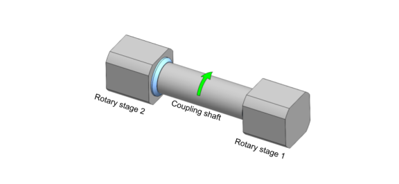
A gantry is a type of mechanical device with two physical axes that are coupled together mechanically and are operating in the same direction. The most common form of gantry is the H-bridge design, where two parallel linear spars are joined by a cross bridge. Gantries can be in other forms such as two coaxial rotary stages coupled together by a shaft.
Figure: Linear H-Bridge Gantry
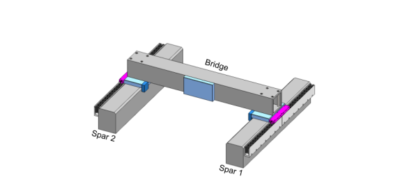
Figure: Rotary Gantry
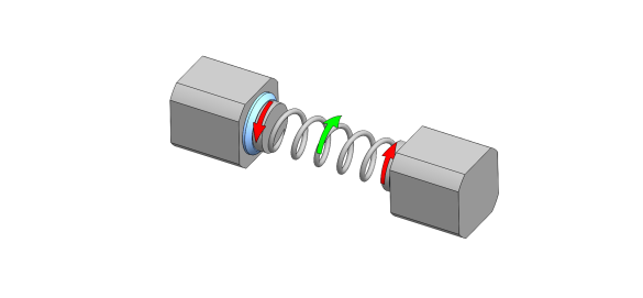
If the mechanical coupling does not allow relative motion between the two axes, then the design is said to be Rigid. If compliance mechanisms like bearings, flexures, or springs allow for some substantial and intentional level of relative motion between the two axes, then the design is said to be Flexible.
Figure: Rigid Linear Gantry
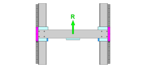
Figure: Flexible Linear Gantry
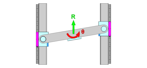
Figure: Rigid Rotary Gantry
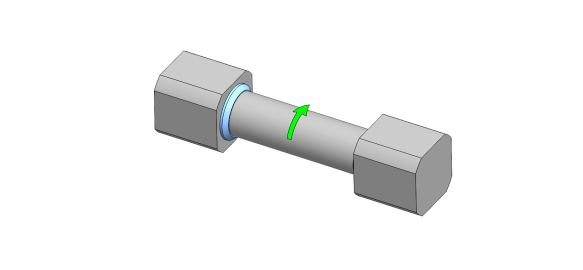
Figure: Flexible Rotary Gantry
Because the linear H-bridge is by far the most commonly used gantry design, this documentation refers to the two coupled axes Spar 1 and Spar 2. The examples will also use the linear H-bridge gantry case.
Gantry Control Methods
Automation1 supplies two methods to control gantries: Decoupling Control and Current Command Coupling Control. Decoupling Control supplies superior dynamic performance and positioning accuracy, but it demands precision alignments and low error motions from the mechanical device. Current Command Coupling Control provides better dynamic performance than single-sided servo control, and it is less demanding than Decoupling Control on the quality or complexity of the mechanical design.
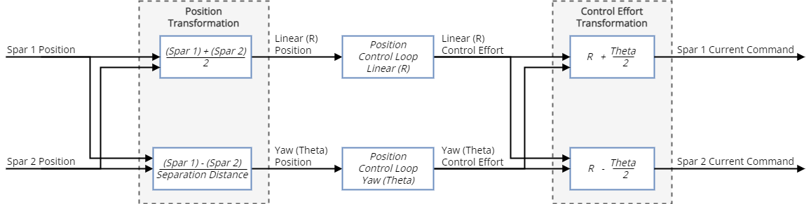
The Decoupling Control method performs coordinate transformation calculations, converting the two physical linear axes into one logical linear axis (R) and one logical rotary axis (Theta). The logical linear (R) position is simply the average of the two physical spar positions. The logical rotary (Theta) position is the difference between the two spar positions divided by the separation distance between the two spars. In an H-bridge gantry design, the logical rotation axis results in yaw motion of the gantry assembly. Decoupling Control is also known as Yaw Control. The position control loops act on the logical Linear (R) and the logical Yaw (Theta) axes and not on the physical axes. Refer to the figure that follows.
Figure: Block diagram of Decoupling Control
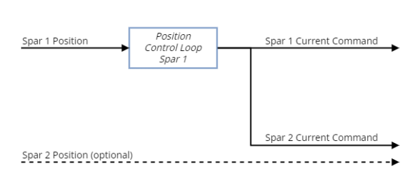
The Current Command Coupling Control method relies on servo control of only one of the two spar axes, Spar 1. The current command from Spar 1 is cloned to the Spar 2 motor through a separate amplifier. An inherent assumption in this scheme is that the Spar 2 amplifier and motor are identical to those of Spar 1. With this method, Spar 1 is under closed-loop control while Spar 2 is under open-loop control. Spar 2 does not require a position sensing device, but if it does have one, it is for informational purposes only. As compared to single-sided closed loop control, Current Command Coupling Control better aligns the center of driving force with the center of moving mass, dramatically reducing excitation of the gantry’s yaw vibrational mode during moves. However, unlike with Decoupling Control, the yaw motion of the gantry is still uncontrolled when using Current Command Coupling Control, so yaw errors and disturbances are unabated by the controller. For this reason, use Current Command Coupling only on Rigid gantries where there is a stiff mechanical connection between the two spar carriages.
IMPORTANT: Aerotech recommends that you use the Current Command Coupling Control method only with direct drive stages.
Figure: Block diagram of Current Command Coupling Control
Configuring Gantry Control
To configure your gantry, use Machine Setup and the How to align the gantry procedure. If you are working with a standard Aerotech gantry, start with Machine Setup. If not, start with Device Catalog to define your gantry and then use that gantry definition in Machine Setup. After you complete Machine Setup, the Checklist will guide you through final configuration and startup activities.
Decoupling Control Parameters
The primary parameters that configure Decoupling Control are as follows:
GantryFeedbackSeparation Parameter
GantryMechanicalDesign Parameter
Some parameters configure the logical axes, while others define the physical nature of the spars or amplifiers. The logical Linear (R) and the physical Spar 1 axes share an axis name for the purposes of organizing parameters, faults, and data collection. Likewise, the logical Yaw (Theta) and the physical Spar 2 axes share an axis name.
For example
If a gantry’s logical linear axis is named Y, then the DefaultAxisSpeed Parameter of Y sets the default speed for the logical linear motion of the gantry, and the value of the PrimaryFeedbackResolution Parameter of Y defines the physical resolution of the Spar 1 feedback device.
Current Command Coupling Control
The primary parameters that configure Current Command Coupling Control are as follows:
Gantry Feedback Configurations
The table that follows shows the feedback configurations supported in Automation1.
Table: Supported Gantry Feedback Configurations
| R Axis Parameters | Theta Axis Parameters | Description |
||
|---|---|---|---|---|
| FeedbackInput0 | FeedbackInput1 | FeedbackInput0 | FeedbackInput1 | |
|
Primary Feedback |
Primary Feedback |
Primary Feedback |
Primary Feedback |
Standard gantry with a single feedback device on each spar. |
|
Primary Feedback |
Primary Feedback |
Auxiliary Feedback |
Primary Feedback |
Dual feedback on Theta axis. The Auxiliary Feedback on the Theta axis is a device used to measure the angle of the gantry. This feedback must be wired to the Auxiliary Feedback input on the Spar 2 drive. |
| Auxiliary Feedback |
Primary Feedback |
Primary Feedback |
Primary Feedback |
Dual feedback on R axis. The Auxiliary Feedback on the R axis is a device used to measure the position of the gantry R axis. This feedback must be wired to the Auxiliary Feedback input on the Spar 1 drive. A typical example of this type of device is a laser interferometer. |
| Auxiliary Feedback |
Primary Feedback |
Auxiliary Feedback |
Primary Feedback |
Dual feedback on both physical axes. This configuration assumes each spar has two physical feedback devices measuring position. |
| Auxiliary Feedback | Auxiliary Feedback | Primary Feedback | Primary Feedback | Gantry with a single feedback device on each spar. |
| Primary Feedback | Auxiliary Feedback | Primary Feedback | Primary Feedback | Dual feedback on R axis. The Primary Feedback on the R axis is a device used to measure the position of the gantry R axis. This feedback must be wired to the Primary Feedback input on the Spar 1 drive. A typical example of this type of device is a laser interferometer. |
Commanding Gantries
For both gantry control methods, use the axis associated with Spar 1 to command linear motion of the gantry.
If you are using the Decoupling Control method, you can also command rotary (yaw) motion on the Yaw (Theta) axis if you are working with a Flexible gantry. In the Rigid gantry case, the yaw of the gantry is controlled as a null axis, meaning that it cannot be commanded to move but that it will actively compensate for errors and disturbances.
Under Decoupling Control, the controller uses a small angle approximation when it computes the Yaw (Theta) position. Thus, the controller accurately approximates the angular difference between the physical axes for values of the Yaw (Theta) position less than approximately 10°, or 0.17 radians.
Gantry Enable Behavior
Gantry enable behavior depends on the gantry configuration and control method.
In the Current Command Coupling Control case, the axis under closed-loop servo control, the leading axis connected to Spar 1, is enabled like any normal axis. The open-loop following axis connected to Spar 2 cannot be enabled, but the Spar 2 amplifier itself will be active when the Spar 1 axis is enabled.
For Flexible gantries using Decoupling Control, the Linear (R) and Yaw (Theta) axes can be enabled and disabled independently.
For Rigid gantries using Decoupling Control, the Linear (R) and Yaw (Theta) axes enable and disable together. That is, if you enable the Linear (R) axis, the controller will simultaneously enable the Yaw (Theta) axis. When this happens, the controller performs an alignment move on Theta to maintain a consistent null position for that axis. The speed and acceleration of the alignment move is set by the HomeSpeed Parameter and HomeRampRate Parameter.
Gantry Home Behavior
In the Current Command Coupling Control case, the axis under closed-loop servo control, the leading axis connected to Spar 1, is homed like any conventional axis. The open-loop following axis connected to Spar 2 cannot be homed.
In the Decoupling Control case, the controller synchronizes homing of the gantry axes. When homing using the home type To Limit and Reverse to Marker, the controller scans for marker signals from both Spar 1 and Spar 2. Once both markers are found, the scan aborts. Then, the controller commands asynchronous moves on the Linear (R) and Yaw (Theta) axes per their HomeOffset, HomeSpeed, and HomeRampRate parameter values. For the Linear (R) axis, the HomeOffset is applied from the average of the two marker positions. For the Yaw (Theta) axis, the HomeOffset is applied from the angle that would land each spar carriage on its marker.
WARNING: When you use Decoupling Control, you must correctly configure the HomeOffset Parameter for the Yaw (Theta) axis before you home the gantry axes. Physical damage and permanent mechanical misalignment of the gantry can occur if the HomeOffset parameter is not set correctly. Use the Do Gantry Alignment section of the Homing module and the applicable values for the GantryMisalignmentThreshold and PositionErrorThreshold parameters to configure your gantry correctly before you try to home it.
Gantry Calibration
In Decoupling Control gantry mode, position calibration occurs on the logical Linear (R) and Yaw (Theta) axes. Calibration of the linear axis compensates for linear error motions, like accuracy error. Calibration of the rotary axis compensates for angular error motions, like yaw or orthogonality.
In Current Command Coupling Control mode, position calibration occurs on the closed-loop axis connected to Spar 1. The open-loop following axis connected to Spar 2 cannot be calibrated.
Gantry Limit Behavior
In both gantry control methods, the controller firmware reads the physical end-of-travel limit signals and then determines and reports the logical limit status.
During Current Command Coupling Control, a physical end-of-travel limit signal on either spar is reported as a logical limit on both spars simultaneously. This is OR logic.
In Decoupling Control mode, logical Linear (R) and Yaw (Theta) limits are inferred from the state of the Spar 1 and Spar 2 physical limits. In the Rigid gantry case, the Linear (R) limits are of primary importance because gantry yaw motion is constrained mechanically, and therefore limits on yaw motion are unnecessary. But, in the case of a Flexible gantry, Yaw (Theta) limits are important and require special consideration. To protect Flexible gantries from exceeding the maximum allowable travel, use a combination of hardware limit signals from the spars, software limits set with the SoftwareLimitSetup Parameter on the logical yaw axis, and the GantryMisalignmentThreshold Parameter on the logical yaw axis.
The physical spar limits protect the spar carriages from impacting the hard stops at the end of spar travel. It is best practice to include electrical limit switch devices on each spar of a Flexible gantry. But, if that is not possible, then on the spar without limit switches, the overtravel between the point when the limit triggers and the point when the carriage impacts the hard stop must be large enough to account for the allowable Theta travel plus the deceleration distance of the gantry.
Figure: Overtravel required on Spar 2 when limits exist only on Spar 1
The table that follows shows how the controller firmware transforms physical limit states into logical limit states.
|
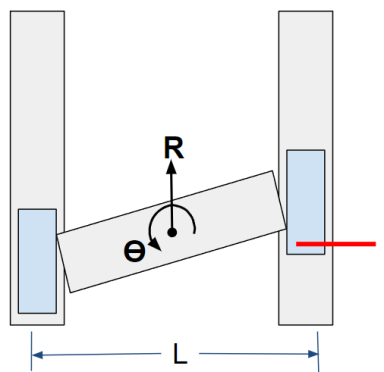
Physical limit condition: Spar 1 positive limit engaged
Logical limit state: Logical R is in the positive (clockwise / CW) limit since that axis can no longer move any further in the positive direction.
Logical Theta is also in the positive (CW) limit since it can no longer rotate any further in the positive direction. |
|
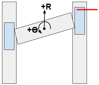
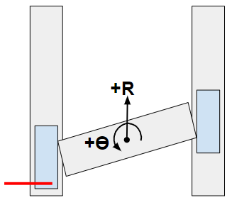
Physical limit condition: Physical Spar 2 negative limit engaged
Logical limit state: Logical R is in the negative (counterclockwise / CCW) limit since that axis can no longer move any further in the negative direction.
Logical Theta is again in the positive (CW) limit since it cannot rotate any further in the positive direction. |
|
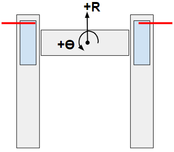
Physical limit condition: Both Spar 1 and Spar 2 positive limits engaged
Logical limit state: Logical R is in the positive (clockwise / CW) limit because that axis cannot move any further in the positive direction.
Logical Theta cannot rotate in either direction without further entering a physical limit, so Theta is in the positive (CW) limit and the negative (CCW) limit at the same time. |
On Flexible gantries, you should also configure Software Limits to prevent commands to the Theta axis from exceeding the mechanical travel of that axis. Use the SoftwareLimitSetup parameter, SoftwareLimitLow parameter, and SoftwareLimitHigh parameter to configure software limits.
WARNING: Software limits have an effect on the axis only after it is homed. If the Theta axis has not been homed, be careful when you command the axis or it can exceed the maximum allowable travel.
Other Gantry Faults
When you use Current Command Coupling Control, faults occur only on the closed-loop axis connected to Spar 1.
In Decoupling Control mode, some of the axis faults are associated with the logical axes. In the case of a logical fault, the controller will report that fault on the applicable logical axis. In the special case of a Rigid gantry under Decoupling Control, if a fault causes one logical axis to disable, the controller will disable the other logical axis.
Logical Faults
-
Position Error Fault
-
CW/Positive End-of-Travel Limit Fault
-
CCW/Negative End-of-Travel Limit Fault
-
CW/High Software Limit Fault
-
CCW/Low Software Limit Fault
-
Maximum Velocity Command Fault
-
Velocity Error Fault
-
External Fault
-
Feedback Scaling Fault
-
Marker Search Fault
-
Safe Zone Fault
-
In Position Timeout Fault
-
Voltage Clamp Fault
-
Internal Fault
There are other faults that are strictly physical. When a physical fault occurs, the controller reports that fault on both of the gantry axes simultaneously.
Physical Faults
-
Over Current Fault
-
Amplifier Fault
-
FeedbackInput0 Fault
-
FeedbackInput1 Fault
-
Hall Sensor Fault
-
Emergency Stop Fault
-
Motor Temperature Fault
-
Amplifier Temperature Fault
-
Encoder Fault
-
Motor Supply Fault
Gantry Positioning Control with Dual Feedback
Placing auxiliary feedback close to the application workpoint is an established way to improve operational accuracy and repeatability of an axis. In a typical scenario, the integral gain of the PID controller operates on the auxiliary feedback error while the derivative gain works on the primary feedback error. Depending on the control loop setup, the proportional gain can operate on either the auxiliary or primary feedback errors. Because the control loop operates on two feedback signals, this is sometimes referred to as dual feedback control or dual loop control.
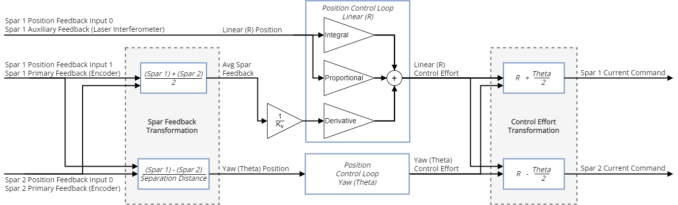
Dual feedback control of gantries is possible with the Decoupling Control scheme. The figures that follow show an example physical arrangement and block diagrams of the dual feedback control schemes for a gantry with laser interferometer feedback on the Linear (R) axis.
Figure: Gantry Stage with Auxiliary Laser Interferometer Feedback and Primary Encoder Feedback
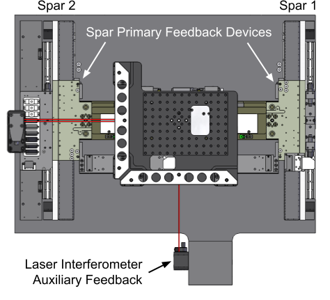
Figure: PID Decoupling Control with Auxiliary Proportional-Integral (PI) and Primary Derivative (D)
For more information on the control of dual feedback systems, refer to Servo Loop Block Diagram - Dual Feedback (Secondary I Only) and Servo Loop Block Diagram - Dual Feedback (Secondary PI).
Useful Visualize Signals for Measuring Gantry Performance
- Position / Velocity / Acceleration Command, Feedback, and Error - these staple commands show logical axis motion
- Primary Feedback - shows raw counts from the physical feedback devices
- Position Calibration All - shows the calibration on the logical axis in counts
- Current Command, Feedback, and Error - these staple commands show physical motor current
- Control Effort - shows the current command to the logical axes
- Drive Feedforward Output - shows the feedforward portion of the Control Effort for the logical axis
- Drive Status - shows a full word or individual bits describing the status of the drive
- Cw End Of Travel Limit Input
- Ccw End Of Travel Limit Input
- Marker Latch
- Power Limiting
- In Position
- Move Active
- Acceleration Phase
- Deceleration Phase
- Dual Loop Active
- Encoder Clipping
- and more...
- Axis Status - shows a full word or individual bits describing the status of the axis
- Homed
- Profiling
- Wait Done
- Homing
- Calibration Enabled 1D
- Calibration Enabled 2D
- Motion Done
- Gantry Aligned
- and more...


