Machine Setup
Machine Setup helps you configure the controller, configure electrical and mechanical devices, define axes, and change units of measurement so that your parameters are set up correctly. It is near the bottom of the Configure workspace menu.
The first time that you connect to a controller, the start screen for Machine Setup comes into view in the main window. You must complete Machine Setup before you use other features of the application with the controller.
Before you use Machine Setup:
- If you purchased integration from Aerotech, you must first connect to your controller and upload the Machine Controller Definition (MCD) file that is provided on your installation media. This MCD file contains Parameters and Machine Setup data that were fully configured and tested at the factory. See the Administration Topic for information about how to upload MCD files.
- If you purchased an Automation1-iPC from Aerotech, you should not need to use Machine Setup. Your machine should be ready to use after all the electrical and mechanical devices are connected.
- Review the list of controllers, stages, and motors that are incompatible with Automation1 before you use Machine Setup. See Supported Hardware.
If you have to close Machine Setup before you have completed it, click Save Progress and Close to keep configuration information that you started. This configuration is not applied to the controller until you complete Machine Setup.
Machine Setup Milestones
The main milestones in Machine Setup include Controller, Electrical Devices, Mechanical Devices, Interconnectivity, and Summary.
Controller
The Controller milestone checks that the controller is in operation by performing a Controller & System Check. It also does a check to make sure that your system is configured for HyperWire.
If you are connected to a PC-based controller and the HyperWire configuration is not OK, you can make selections to configure the software to use HyperWire cards that are fully installed and configured to operate with Automation1. See Configure the HyperWire Card for more information.
If you want to run the controller virtually without connected mechanical or electrical devices, click Switch to Virtual. For more information about virtual controllers, see Virtual Axes.

If you want the controller to run with HyperWire, click Switch to HyperWire.

Click Next to configure more options for your controller.
The Controller milestone lets you give your controller a name. It also lets you configure startup options for the controller.
If you are connected to a drive-based controller, you can automatically start and initialize Program Automation when you power on the controller. To enable this behavior, use the Automatically Start Controller toggle. If you are connected to a PC-based controller, you can automatically start and initialize Program Automation when you log into the computer where the iSMC is installed. To enable this behavior, use the Automatically Start Controller toggle.
If the Automatically Start Controller toggle is disabled, which is the default setting, the controller does not start until it is required. For example, the controller starts when you open Automation1 Studio and connect to the controller.
If you are connected to a drive-based controller, the Controller milestone shows the date and time of the system clock of the controller. To set the system clock, use Machine Setup with one of the methods that follow:
- Synchronize the system clock with the clock on your PC. To do this, click Sync with PC.
- Manually set the date and time on the system clock. To do this, expand the Set manually menu.
- Synchronize the system clock by using the Network Time Protocol (NTP).
You can complete the Controller milestone after the controller is running. Click Next to go to the Electrical Devices milestone.
The controller cannot start if your connected electrical devices have a channel conflict. You can go to the Electrical Devices milestone to resolve channel conflicts and start the controller.
The controller cannot start if your connected electrical devices require a software or firmware update. You must close Machine Setup and go to the Controller tab in the to make these updates. For instructions about how to update the software and firmware, see the
Electrical Devices
The Electrical Devices milestone lets you identify and review the configuration of electrical devices that are connected to your controller. For PC-based controllers, these are the electrical devices that are connected to the HyperWire card. For drive-based controllers, these are your drive-based controller and the other electrical devices that are connected to it over HyperWire. You can also add and configure information for electrical devices that you will connect at a later time.
Machine Setup alerts you when your electrical devices are not assigned unique channels. Click Auto-Assign Channels to automatically assign unique channels to each device. Click Configure Channels if you want to manually configure the channels.
If you don’t see an electrical device, check that it is powered on and connected and click Refresh. To help identify your devices, click the LED icon on any device in the diagram to make the LEDs on the physical device flash.
Click Next to review the configuration for each electrical device.
If you don’t have your electrical devices yet, you can still click Next and click Add Device. Machine Setup will prompt you for information about the devices that you want to configure. Select your device name and configuration options and click Add.
Review the information for each electrical device. Machine Setup will automatically select options it detects from connected devices.
Click Next to continue to the Mechanical Devices milestone.
Mechanical Devices
The Mechanical Devices milestone lets you select a stage or a motor and lets you select information about your device.
Click Add Device to select the name of the mechanical devices that you want to use. You can filter the list of devices by entering the name of the device. You can decrease the number of items by choosing a device category from the drop-down menu. You can also include or exclude devices from the library of Aerotech Standard Products or from any Device Catalog libraries that you created by checking or clearing the checkboxes in the Include devices from input box. If you have not yet defined your custom device and do not want to exit Machine Setup, the Additional Options link allows you to add custom devices to a Device Catalog library from within Machine Setup.
Select the stage or motor and click Add.
If you want to add another mechanical device, click Add Device.
Click Next to continue to the Interconnectivity milestone.
Interconnectivity
The Interconnectivity milestone lets you assign a mechanical device to an electrical device. When you do this, the application defines the assigned pair as an axis. You can also edit the axis name, units, feedback multiplication factor, programming direction, and feedback connections between the mechanical device and electrical device.
To assign a mechanical device to an electrical device, drag a stage or motor box from the right side of the screen and drop it into the blue box labeled, Place Mechanical Device.
Use the arrows or click on the nodes above the name of the electrical device to select your other electrical devices and assign a mechanical device to each of them.
After you assign your electrical and mechanical devices to define an axis, you can set the axis name, programming units, and multiplication factor for sinusoidal feedback devices. You can use the Inverted (on/off) toggle to set the programming direction of each axis. You can also see the feedback connections and effective encoder resolutions. If the axis has dual feedback, you can use the Swap button to change the feedback connections to how you will configure your feedback cabling. For more information on how Machine Setup selects the default feedback connections, see Dual Feedback Overview.
If the mechanical device of an axis includes a stepper motor under servo control, you can configure the number of microsteps per step by entering a value or by clicking the Calculate button to calculate a recommended number of microsteps. See the StepperMicrostepsPerStep Parameter for more information.
If the axis has a voice coil motor or a DC brush motor and the motor output connector of the drive supports wiring the motor to the bus return, you must select the Wiring Type for the motor. If your motor is connected between amplifier phases A and C, select A to C. If your motor is connected between phase A and the return connection, select A to Return. For more information, refer to the hardware manual for your drive.
If the axis has a servo loop or a digital current loop, you can also configure custom loop targets to adjust the gains you want to have on the axis. Use the Set Custom Gains link to open the screen that lets you customize the Phase Margin or Crossover Frequency for one of the available loops. During parameter calculations, Machine Setup applies more or less aggressive gain parameters to get these targets. For more information about the effect of servo and current loop gains on an axis, see Digital Current Loop Block Diagram and Servo Loop.
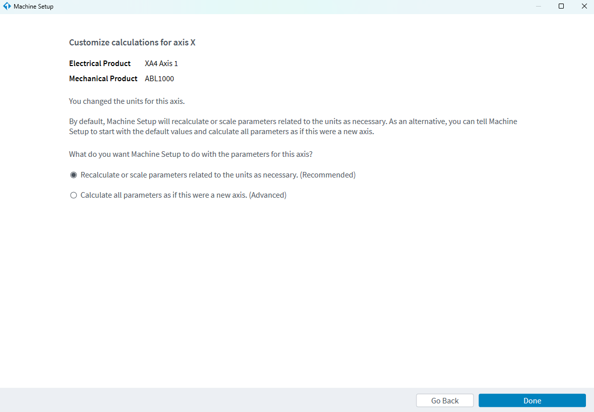
After you define each axis, click Next to continue to a summary of the Interconnectivity milestone. If you used Machine Setup to make changes to an existing, configured axes, you can click the More Options link to select how you want Machine Setup to calculate the parameter changes for the axis.
CAUTION: If you do not use the recommended option to recalculate or scale parameters, you can lose work.
Specification Updates in the Interconnectivity Milestone
If specifications changed for a configured axis or axes since the last time you used Machine Setup, the Interconnectivity summary shows that changes occurred.
Specification updates for standard Aerotech products can only occur after an Automation1 version change. Specification updates from a version change do not cause Machine Setup to automatically calculate new parameter values for the configured axis. If you do not use the recommended option to recalculate or scale parameters, the specification updates are included in parameter calculations.
You can change the specifications of a device in an open Device Catalog. Machine Setup applies those updates by calculating new parameter values for the configured axis. If you do not want the changes have an effect on Machine Setup, use the procedure that follows.
-
From the Interconnectivity summary screen, which indicates specifications have been updated on an axis using the device catalog device, click Save Progress and Close to exit Machine Setup.
-
Click Device Catalog in the sidebar of the Configure workspace.
-
Select the catalog tab that contains the device that was configured in Machine Setup.
-
Click the checkbox to the left of the device configured in Machine Setup.
-
Click the Pencil icon to edit the specifications of this device.
-
Revert any changes made to the device since the last time it was configured in Machine Setup.
-
Click Save Device to save the edits to the device.
-
Click the Add New Device button and select New Mechanical Device to create a new device in the same catalog. The Add a non-standard mechanical device screen comes into view.
-
Select the category from the Device category drop-down. This must be the same as the existing device category.
-
Add a name to Device name field. This should be different from the existing device name.
-
Click the Next button to go to the next screen.
-
Select the Copy and edit a device option and select the existing catalog device as the source. Click the Next button.
-
On the Enter or modify specifications screen, change only the specifications that differ from the existing device. See Device Catalog and Define a Non-Standard Device for more information about this process.
-
Return to Machine Setup and complete configuration using the original device, which now no longer contains any specification updates.
-
In the future, use the new version of the device when adding devices to Machine Setup.
Defining a Gantry Axis in the Interconnectivity Milestone
If one or more of your unassigned Mechanical Devices are gantries, you will be prompted to define those gantry axes when you get to the Interconnectivity milestone.
- On the Interconnectivity - Define Gantries prompt screen, click the Yes button.
- Use the drag-and-drop feature to assign available electrical devices with the mechanical gantry devices.
- Click Done to continue the Machine Setup workflow.
After you define your gantry axis, the Interconnectivity milestone shows each of your gantries in the device list on the right of the screen. To make changes to the axis definitions of fully defined gantry axes, click the Edit button next to a gantry in the device list. If the gantry axes are not fully defined, click the Resume button to complete the process.
The two spars of the gantry must have the same programming direction. If the hardware feedback directions of the two spars are different, click the Inverted toggle on one of the spars to enable it.
For more information on gantry devices, see Gantry Systems Overview.
Summary
The Summary screen shows you the configuration of the axes that you defined.
If you have axes that were defined before this Machine Setup session, the Summary screen also shows how these axes changed and how parameters will be calculated because of the new changes.
Click the View Changes button in the Details column to see the category, name, current value, and new value of the parameters. You can deselect a parameter to not use the new value that was calculated. Click Complete Machine Setup to save the parameters and reset the controller.
Refer to Axis Updates and Parameter Calculations in Machine Setup for more information on the types of changes that Machine Setup can calculate for specified subsets of parameters.
Recommended Next Steps
Complete the items in the Checklist tab of the application sidebar. The Checklist guides you through applicable tasks for your types of devices. Some common Checklist items are:
- Review and make any necessary changes to the Protection parameters for each axis.
- Faults
- Limits
- Brake
- Thresholds
- Rates
- Use the Motor Hall & Signal Status Module to make sure that the controller is correctly reporting the status of different key inputs.
- Use the Motor Phasing Module to automatically detect and compensate for motor wiring problems.
- If your axes are configured for absolute encoder feedback, use the Absolute Encoder Alignment Module to automatically determine the Commutation Offset.
- Configure the Homing parameters for each axis.
- Use the Automatic Encoder Tuning Module for each axis with an analog encoder.
- If you have a gantry under Decoupling Control, you must do an alignment and configure the HomeOffset Parameter for a valid Yaw (Theta) axis before you home the gantry axes. For information about how to do an alignment, see the Do Gantry Alignment section of the Homing module.
- Use the EasyTune Module to configure gains and filters for each servo axis.
Machine Setup adds items to the Checklist tab after you define an axis for the first time. When you complete an item, select the checkbox to remove it from the Checklist. If you want to restore items, click Start Over from the menu at the top of the Checklist tab.


