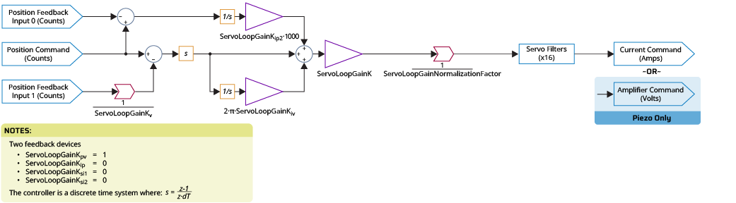
Servo Loop Block Diagram - Dual Feedback (Secondary I Only)
The diagram that follows shows the servo loop for a dual feedback secondary I controller.
An alternate method to dual feedback control is shown in Servo Loop Block Diagram - Dual Feedback (Secondary PI). Typically, the Secondary PI method is higher performing, but it requires a relatively high resolution Auxiliary feedback device with a tight structural loop. If it is difficult to get stability with the Secondary PI method, use to the Secondary I Only method, which is more robust.
The units of the servo loop output depend on the type of axis being controlled. Refer to the table that follows.
Table: Servo Loop Axis Type, Output, and Units
| Axis Type | Servo Loop Output and Units |
|---|---|
|
Piezo axis |
Amplifier command in Volts. |
|
Stepper axis |
Commutation angle in microsteps. |
|
All other axes |
Current command in Amps. When the servo loop output is a current command, the current loop is used to generate the amplifier command in Volts. For more information, refer to Digital Current Loop Block Diagram. |
IMPORTANT: The units of ServoLoopGainK Parameter are determined by the ServoLoopGainNormalizationFactor. If ServoLoopGainNormalizationFactor is configured correctly, the units of ServoLoopGainK are in engineering stiffness units ([N/mm], [(Nm/rad], etc.). Refer to ServoLoopGainNormalizationFactor Parameter for more information.
Tip: For information on how to set the parameters, refer to the Help topic for each parameter.
Figure: Servo Loop Block Diagram - Dual Feedback Secondary I Only