Axes Category Overview
In the Configure workspace, use the Axes category to configure axes and parameters, interact with the controller to tune axes, and configure motor phasing, encoder feedback, and homing.
Topics in the Axes category have an Axis drop-down box in the topic toolbar at the top, where you can select the axis you want to configure. Click the Manage Axes link to configure the axes and show or hide them in the application.
Each topic in the Axes category lets you directly edit axis parameters. Some topics also have helper modules with a user Interface to lets you interact with the controller to automatically calculate parameter values.
IMPORTANT: These parameters might command motion on the selected axis.
- Make sure the conditions are safe for motion to occur on the selected axis.
- Make sure that the selected axis is away from end-of-travel and software limits.
- Make sure that nothing blocks the selected axis.
For more information about how to edit parameters in the Axes category, see Parameters.
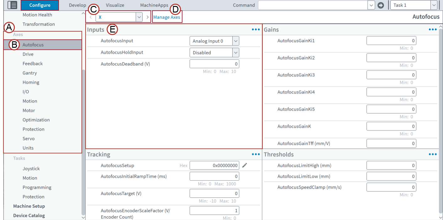
Table: Axes Category
| Image Label | Name | Type | Description |
|---|---|---|---|
|
|
Axes |
Category |
The Axes category of the Configure workspace contains all the topics that help you configure axes. |
|
|
Autofocus |
Topic |
Autofocus is one of the topics in the Axes category. Select a topic to use the related modules. |
|
|
Axis selector |
Drop-Down Box |
Use the axis selector on the topic toolbar to select the axis you want to configure. Use the Manage Axes dialog to show a configured axis. Use Machine Setup to configure new axes. |
|
|
Manage Axes dialog |
Link |
Click this link on the topic toolbar to use the Manage Axes dialog. For more information, refer to Table: Manage Axes Dialog. |
|
|
Inputs |
Module |
Inputs is one of the modules in the Autofocus topic. Use each module to configure specific parameters related to the topic. |


| Image Label | Name | Type | Description |
|---|---|---|---|
|
|
Index |
Box |
Shows the axis index. |
|
|
Name |
Text Box |
Specify the name of the axis. |
|
|
Decimal Places |
Text Box |
Specify the number of decimal places to show in the Axis Dashboard. |
|
|
Virtual |
Box |
Identifies the axis as virtual or physical. Virtual axes show a check mark. Physical axes do not show a symbol. |
|
|
Machine Setup Configured |
Box |
Shows the Machine Setup configuration for the axis. Axes configured in Machine Setup show a check mark. Axes that are not configured in Machine Setup do not show a symbol. |
|
|
Display |
Toggle |
Specify if the application shows or hides the axis. |

For information about the topics in this category, see the pages that follow:
- Autofocus Topic: Configure the behavior of the axes when autofocus is enabled. You can configure inputs, the autofocus loop, gains, and thresholds.
- Drive Topic: Configure the current loop, current command coupling, virtual drive options, and the communication protocol of the connected galvo scanner.
- Feedback Topic: Tune encoder signals for analog feedback devices and adjust the encoder gain, offset, and phase patterns. Manual and automatic tuning are available.
- Gantry Topic: Configure axes that are coupled together mechanically.
- Homing Topic: Configure the homing behavior for axes. The Homing module can automatically select the recommended home type for each axis.
- IO Topic: Configure options related to inputs and outputs. Specify filters and offsets for analog inputs.
- Motion Topic (Axes Category): Specify parameters for axis type, direction, motion defaults, thresholds, and other related features.
- Motor Topic: Automatically detect and compensate for motor wiring problems when you are using mechanical devices with AC brushless motors. You can also determine the Commutation Offset and make sure the controller correctly reports different inputs.
- Optimization Topic: Specify configurations for the Enhanced Throughput Module (ETM), Enhanced Tracking Control, the Cross-Axis Feedforward controller-level algorithm, Command Shaping, Harmonic Cancellation, and Enhanced Scanner Control (ESC).
- Protection Topic (Axes Category): Specifies options for fault reporting, fault response, thresholds, brakes, and limits.
- Servo Topic: Servo tune an axis. It is typical to use two or three tuning tools during this process. They include EasyTune, Closed Loop Tuning, Open Loop Tuning, Manual Servo Tuning, and the Frequency Response module.
- Units Topic: Configure parameters for how units are used and displayed.


