Motor Topic
Use the Motor topic to automatically detect and compensate for motor wiring problems. You can also make sure the controller reports the correct status for different inputs and determine the commutation![]() The action of steering currents to the proper motor phases to produce optimum motor torque/force. In brush-type motors, commutation is done electromechanically via the brushes and commutator. A brushless motor is electronically commutated using a position feedback device such as an encoder or Hall effect devices. Stepping motors are electronically commutated without feedback in an open-loop fashion. offset for axes that use absolute encoder feedback. This topic and its
The action of steering currents to the proper motor phases to produce optimum motor torque/force. In brush-type motors, commutation is done electromechanically via the brushes and commutator. A brushless motor is electronically commutated using a position feedback device such as an encoder or Hall effect devices. Stepping motors are electronically commutated without feedback in an open-loop fashion. offset for axes that use absolute encoder feedback. This topic and its
IMPORTANT: When you use a helper module to edit parameters automatically, make sure you are in Basic Editing mode. To edit parameters manually, click Go to Advanced Editing on the top right of the Configure workspace.
Motor Phasing Module
IMPORTANT: Use this module only with mechanical devices that have AC brushless motors. This module does not support mechanical devices that have gantry axes.
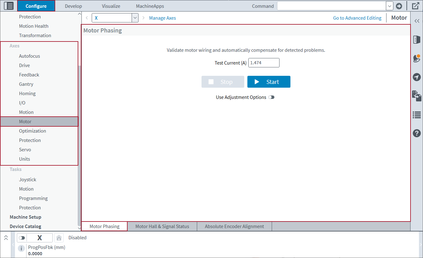
Use the Motor Phasing module to automatically detect and compensate for motor wiring problems. This module can have an effect on the FeedbackSetup Parameter, CommutationInitializationSetup Parameter, and CommutationOffset Parameter. To use this module, make sure that you are in the Basic Editing mode.
The Motor Phasing module automatically sets the test current to 50% of the value of the AverageCurrentThreshold Parameter. If the module cannot calculate results, the test current value might be too low.
IMPORTANT: Make sure that it is safe for motion to occur on the specified axis. Also, make sure that the specified axis is away from end-of-travel limits and software limits.
Click the Start button. While the axis travels one full electrical cycle, the calculator collects data and calculates the parameter results.
Adjustment Options
You can use the adjustment options to increase the effectiveness of the Motor Phasing module. Make sure that you use the default options the first time you use the module on an axis. If you get unsatisfactory results from the default options, specify a larger step interval or a smaller step size to get more accurate results.
- In the Configure workspace, find the Axes category. Then select the Motor topic.
- Make sure that you are in the Basic Editing mode.
- At the bottom of the topic, select the Motor Phasing tab.
- Select the Use Adjustment Options toggle.
- Specify a value for the step delay. The step delay is the quantity of time, in milliseconds, that the calculator waits to let the encoder settle after the axis moves to a new angle in the electrical cycle.
- Specify a value for the step size. The step size is the number of degrees in the electrical cycle that the axis steps. If you specify a smaller value for step size, the calculator collects higher-resolution data.
- Click the Start button. The Motor Phasing module uses the adjustment options while it travels one full electrical cycle and collects data. When motor phasing is completed, parameter changes that compensate for motor wiring are applied to the controller.
- To keep these parameter changes active after the next controller reset, you must save them to the controller. Click Save All on the left panel of the Configure workspace.
Motor Hall & Signal Status Module
IMPORTANT: Use this module only with mechanical devices that have AC brushless motors.
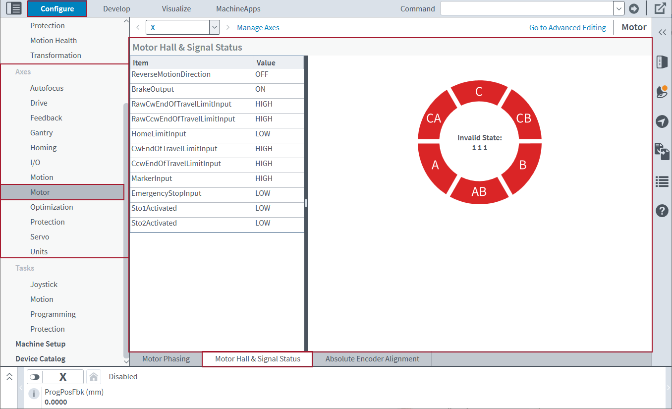
Use the Motor Hall & Signal Status module to make sure that the controller is correctly reporting the status of different key inputs. To use this module, make sure that you are in the Basic Editing mode.
This module does not command motion. Thus, you can use it to make sure that the input status is correct. If you think that your axis is not safe to enable, you can continue to use this module to examine the input status and make sure that it is correct.
Use the table of input signals to make sure that changes to standard motion are applied correctly. Changes include travel limits, brakes, and the ReverseMotionDirection Parameter. The input signals will update when manual or commanded motion is executed on the axis.
Use the Hall Status indicator to make sure that these operations are done correctly:
- Each Hall State is identified during the course of motion.
- Motion is executed in the expected direction relative to the Hall Sequence.
The Hall Status indicator will update when manual or commanded motion is executed on the axis.
Absolute Encoder Alignment Module
IMPORTANT: This module does not support mechanical devices that have gantry axes.
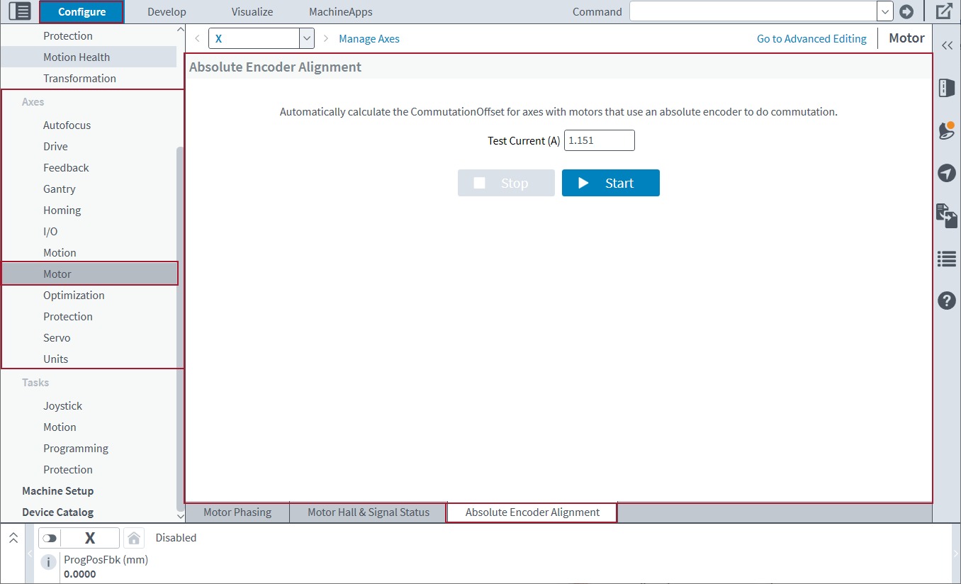
Use the Absolute Encoder Alignment module to automatically determine the Commutation![]() The action of steering currents to the proper motor phases to produce optimum motor torque/force. In brush-type motors, commutation is done electromechanically via the brushes and commutator. A brushless motor is electronically commutated using a position feedback device such as an encoder or Hall effect devices. Stepping motors are electronically commutated without feedback in an open-loop fashion. Offset for axes that use absolute encoder feedback for commutation
The action of steering currents to the proper motor phases to produce optimum motor torque/force. In brush-type motors, commutation is done electromechanically via the brushes and commutator. A brushless motor is electronically commutated using a position feedback device such as an encoder or Hall effect devices. Stepping motors are electronically commutated without feedback in an open-loop fashion. Offset for axes that use absolute encoder feedback for commutation![]() The action of steering currents to the proper motor phases to produce optimum motor torque/force. In brush-type motors, commutation is done electromechanically via the brushes and commutator. A brushless motor is electronically commutated using a position feedback device such as an encoder or Hall effect devices. Stepping motors are electronically commutated without feedback in an open-loop fashion.. To use this module, make sure that you are in the Basic Editing mode.
The action of steering currents to the proper motor phases to produce optimum motor torque/force. In brush-type motors, commutation is done electromechanically via the brushes and commutator. A brushless motor is electronically commutated using a position feedback device such as an encoder or Hall effect devices. Stepping motors are electronically commutated without feedback in an open-loop fashion.. To use this module, make sure that you are in the Basic Editing mode.
When you use this module, the axis that you specify must have the configurations that follow:
- An AC brushless motor.
- The FeedbackInput1 Parameter must be set to Primary Feedback or Auxiliary Feedback.
- The feedback device that the FeedbackInput1 parameter applies to must use absolute feedback.
This module makes sure that the Initialization Method bit is set to Absolute Encoder for the CommutationInitializationSetup Parameter. It also sets the value of the CommutationOffset Parameter to the Commutation![]() The action of steering currents to the proper motor phases to produce optimum motor torque/force. In brush-type motors, commutation is done electromechanically via the brushes and commutator. A brushless motor is electronically commutated using a position feedback device such as an encoder or Hall effect devices. Stepping motors are electronically commutated without feedback in an open-loop fashion. Offset that it calculates. This module will detect motor phasing. If necessary, it sets the Primary Feedback Direction or Auxiliary Feedback Direction bit of the FeedbackSetup Parameter.
The action of steering currents to the proper motor phases to produce optimum motor torque/force. In brush-type motors, commutation is done electromechanically via the brushes and commutator. A brushless motor is electronically commutated using a position feedback device such as an encoder or Hall effect devices. Stepping motors are electronically commutated without feedback in an open-loop fashion. Offset that it calculates. This module will detect motor phasing. If necessary, it sets the Primary Feedback Direction or Auxiliary Feedback Direction bit of the FeedbackSetup Parameter.
The Absolute Encoder Alignment module automatically sets the test current to 50% of the value of the AverageCurrentThreshold Parameter. The test current might be too low if the module cannot calculate the results.
IMPORTANT: Make sure the conditions are safe for motion to occur on the specified axis. Also, make sure that the specified axis is away from end-of-travel limits and software limits.
- In the Configure workspace, find the Axes category. Then select the Motor topic.
- Make sure that you are in the Basic Editing mode.
- At the bottom of the topic, select the Absolute Encoder Alignment tab.
- Click the Start button. The motor moves to specific electrical angles. The module collects data and calculates the Commutation
 The action of steering currents to the proper motor phases to produce optimum motor torque/force. In brush-type motors, commutation is done electromechanically via the brushes and commutator. A brushless motor is electronically commutated using a position feedback device such as an encoder or Hall effect devices. Stepping motors are electronically commutated without feedback in an open-loop fashion. Offset.
 - When the Absolute Encoder Alignment process is complete, the parameter changes are applied to the controller. To keep these parameter changes active after the next controller reset, you must save them to the controller. Click Save All on the left panel of the Configure workspace.
Advanced Editing
If you must edit the


