Device Catalog
Use the Device Catalog module to define mechanical devices and galvo lenses that are not standard Aerotech products. Catalogs can contain one or more devices. You can use the devices in your open catalogs as you configure axes in Machine Setup. You can also add new catalog devices directly from Machine Setup.
You can define the types of mechanical devices that follow in a catalog:
- Direct Drive Linear Stage
- Screw Drive Linear Stage
- Direct Drive Rotary Stage
- Gear Drive Rotary Stage
- Rotary Motor
- Gantry
- Galvo Laser Scan Head
The galvo lenses that you define in a catalog are available as you configure a galvo scanner in Machine Setup.
To create a device, you can enter all specifications manually, or you can copy and edit an existing device. You can also move or copy devices between open catalogs.
Enter Specifications Manually
When you create a new galvo lens or mechanical device, if you want to manually enter all required specifications, select the Enter specifications manually option on the Select source device: step. See the Define a Non-Standard Device page for more information on the specifications expected in this case.
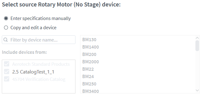
Tip: When you create a new mechanical device with multiple components (i.e., a stage with a motor), you can copy motor specifications from an existing device if you enter specifications for the stage manually.
Copy from an Existing Device
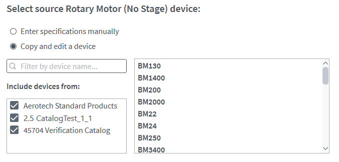
You can define a custom device based on an existing device of the same type. To do this, select the Copy and edit a device option on the Select source device: step. This will copy all necessary specifications from the selected device, which gives you a starting point for entering custom specification values. You can select either a standard device or another custom device as the starting point for the new device. Use the device name field or the checkboxes in the Include devices from: field to filter which devices are shown.
IMPORTANT: When you define a non-standard galvo lens, specifications can be copied only from another non-standard lens or entered manually.
When you copy a motor device, the feedback information included on that motor will also be copied and available in the feedback definition step.
IMPORTANT: When you Copy and edit an existing device, the device you copy and the device you create are not linked. When you edit one device, Device Catalog does not automatically update the other. You must manually edit each device to change its specifications.
Work with Catalogs
Device catalogs are saved as files on either the Windows file system or the controller file system. Automation1 Studio applications on more than one PC can use the same catalog file that is saved to a shared Windows file system location. Catalog files that you save to the controller file system are automatically available to use in Machine Setup by any Automation1 Studio application that connects to the controller. The catalog files saved to the controller file system can be included as you download and upload MCD files for your controller.
Create a Catalog
To create a new catalog, click New Catalog.... Enter a name for the catalog. You can enter a description for the catalog, but that is optional. Click Choose Location and select the folder where you want the catalog file to be created. Enter a file name and click Save, then click Create Catalog.
Open a Catalog
To open a catalog, click Open Catalog.... Go to the folder where the catalog file is located, select it, and then click Open.
Rename a Catalog
To rename a catalog, click Manage Catalogs. The Manage Catalogs dialog comes into view. Use this dialog to change the names and descriptions of any open catalog. When you are done, click OK.
Save a Catalog
After you rename a catalog, change its description, or add or edit devices, select the catalog and click Save Catalog to save it. If you close Studio or close the catalog without saving, you will lose unsaved changes.
Close a Catalog
To close a catalog, click Manage Catalogs. The Manage Catalogs dialog comes into view. In the Actions column, click Close Catalog for the catalog you want to close. When you are done, click OK.
Delete a Catalog
To delete a catalog, click Manage Catalogs. The Manage Catalogs dialog comes into view. In the Actions column, click Delete Catalog for the catalog you want to delete. When you are done, click OK.
Configure an External Stepper Driver
You can use the clock and direction outputs on an SI4 electrical device or on an iXI4 or XI4 (when the XI4 Stepper Mode setting of the ServoLoopSetup Parameter is set to Clock/Direction Outputs) to control an external stepper motor. You must use the Device Catalog to define a Stepper Driver that describes the external stepper motor. In the Device Catalog you must:
- Add a mechanical device that uses a rotary motor. You can create a new device or copy from an existing device.
- When you configure the Motor Type option for the device, you must select Stepper Driver and enter the motor and feedback specifications.
Configure a Galvo Laser Scan Head
You can use a GI4 electrical device to control a Galvo Laser Scan Head that has a protocol interface. You must use the Device Catalog to configure this device. The Device Catalog supports the scan head that follows:
- XY2-100 Scanner Protocol with 16-Bit resolution
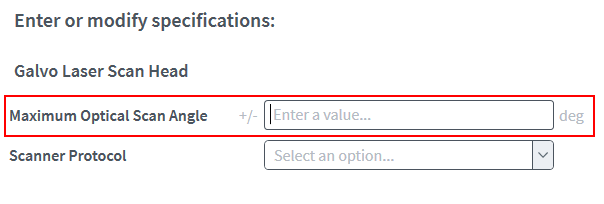
When you configure this device, you must enter the maximum optical scan angle. The value of this angle specifies the typical angular deflection of the scan head. The typical angular deflection is the maximum controllable optical angle, which can occur in the positive or negative direction.
Enter the value of the Maximum Optical Scan Angle as the positive number of degrees, in one direction, from the center to the edge of the range of the scan head.
Configure a Gantry
If you are configuring a gantry, see Gantry Systems Overview for a description of the gantry control methods available in Automation1.
When you configure a gantry, you define properties of the gantry assembly, and you define properties associated with the individual mechanical axes of the gantry. The Device Catalog workflow will guide you through the process. After you define and save the gantry device, it is available for use in Machine Setup.
IMPORTANT: The Device Catalog workflow currently supports configuration of direct-drive linear gantries. For other gantry types, use direct parameter editing to configure your device.
Decoupling Control Method
If you plan to use the Decoupling Control method for your gantry, you must have some information about the construction of the gantry assembly. Be prepared with the information listed below before you start your Device Catalog session. Refer to the image that follows.
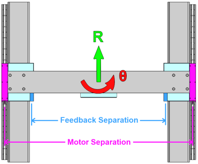
Feedback separation distance: For a rigid gantry, specify the distance between the spar feedback devices in millimeters. For flexible gantries, specify the distance between the rotational joints that connect the bridge to the spar carriages. Machine Setup uses this information to calculate the Yaw (Theta) resolution and the initial servo gains for the Yaw (Theta) axis.
Motor separation distance: Specify the distance between the spar motors in millimeters. Machine Setup uses this information to calculate the initial servo gains for the Yaw (Theta) axis.
Allowable relative error between spars: Specify the maximum allowable error between the spar carriages in microns. This value is particularly important with rigid gantries, where excessive error of the Yaw (Theta) axis might cause mechanical misalignment of the gantry assembly. The GantryMisalignmentThreshold Parameter help topic provides more information and instructions on how to set an initial value.
Linear (R) axis moving mass: Specify the moving mass of the linear axis of the gantry in kilograms. This includes the mass of each spar carriage plus the mass of the bridge assembly. It does not include any extra mass that may be attached to the bridge axis carriage; you will enter that value as a payload during Machine Setup. Machine Setup uses this information to calculate the initial servo gains for the Linear (R) axis.
Yaw (Theta) axis rotational inertia: Specify the mass moment of inertia for the Yaw (Theta) axis about its center of mass in kg·m2. This includes the inertia due to the spar carriages and the bridge assembly. If you know the inertia value, enter it. But if you do not, Device Catalog has a button to estimate a value based on the Linear (R) moving mass and the separation distances that you previously entered. Machine Setup uses this information to calculate the initial servo gains for the Yaw (Theta) axis.
Yaw (Theta) axis rotational stiffness: For a rigid gantry, specify the rotational stiffness of the Yaw (Theta) axis in N·m/μrad. Typical values range from 0.25 N·m/μrad for a low-stiffness gantry to 5.0 N·m/μrad or more for a high-stiffness gantry. Machine Setup uses this information to calculate the initial servo gains for the Yaw (Theta) axis. Rotational stiffness is not required for a flexible gantry.
If you are unsure of the gantry stiffness value, we recommend that you use this procedure to measure the stiffness:
Figure: Example Gantry Stiffness Measurement
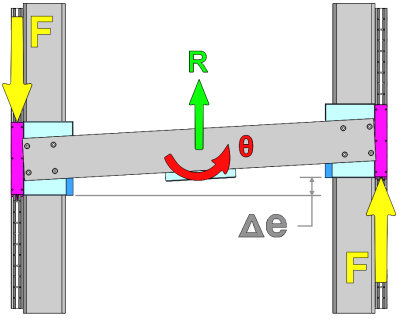
- Apply a known force F to the gantry assembly at the motors as shown.
- Measure the relative displacement between the spar carriages, Δe.
- Perform the following calculations:
- Torque = T [N·m] = F [N] · (Motor Separation Distance [mm] / 1000)
- Angular displacement = Δθ [μrad] = Δe [μm] / (Feedback Separation Distance [mm] / 1000)
- Angular Stiffness = T / Δθ [N·m/μrad]
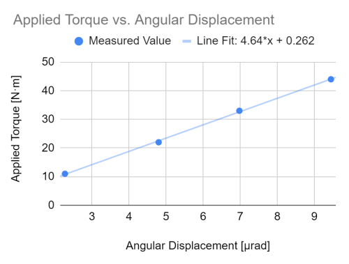
- We recommend applying several torque values, measuring the corresponding displacements, plotting torque versus displacement, and fitting a line to the results. The slope of the line corresponds to the stiffness of the gantry. See the example plot below:
Current Command Coupling Control Method
When you configure Current Command Coupling Control for your gantry, be aware of the following information before you start your Device Catalog session.
Spar 2 feedback device: With current command coupling control, position sensing on spar 2 is unnecessary and therefore optional. During the Device Catalog session for Current Command Coupling Control, you will be prompted to enter a resolution for the spar 2 feedback device. If there is no feedback device on spar 2, then the value you enter for the spar 2 feedback resolution is unimportant, and you use the values from spar 1 for consistency during that step.
Spar 2 commutation: By default, Machine Setup configures the spar 2 axis to commutate from the spar 1 feedback device. But, if you do have a feedback device on spar 2 and want to commutate the spar 2 motor from it instead, set the Update Method of the CommutationInitializationSetup Parameter to Feedback Device for that axis. For more information about setting up motor commutation, see CommutationOffset Parameter and CommutationInitializationSetup Parameter.


