Installation Overview
The images that follow show the order in which to make connections and settings that are typical to the iXL5e/XL5e. If a custom interconnect drawing was supplied with your system, that drawing is on your Storage Device and shows as a line item on your Sales Order in the Integration section.
Figure: Installation Connection Overview for the iXL5e
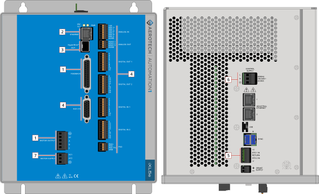
| 1 |
Connect the motor to the amplifier Motor Output connector. |
|
|
Connect the motor to the amplifier Feedback connector. |
||
| 2 |
Connect the PC to the USB or Ethernet port. |
N/A |
| 3 |
Connect the next drive in the system to the HyperWire Out port. |
|
| 4 |
Connect additional I/O as required by your application |
|
| 5 |
Connect the Safe Torque Off (STO). |
|
| 6 |
Connect the power supply to the Control Supply connector. |
|
| 7 |
Connect the motor power to the Motor Supply connector. |
Figure: Installation Connection Overview for the XL5e
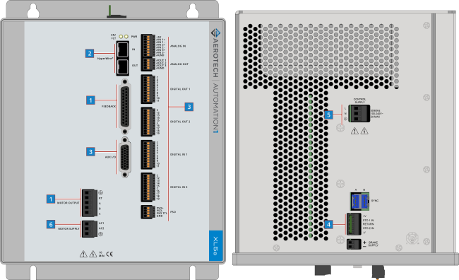
| 1 |
Connect the motor to the amplifier Motor Output connector. |
|
|
Connect the motor to the amplifier Feedback connector. |
||
| 2 |
Connect a PC or drive-based controller HyperWire port to the HyperWire In port. |
|
| 3 |
Connect additional I/O as required by your application |
|
| 4 |
Connect the Safe Torque Off (STO). |
|
| 5 |
Connect the power supply to the Control Supply connector. |
|
| 6 |
Connect the motor power to the Motor Supply connector. |