Motor Power Output Connector
DANGER: Before you do maintenance to the equipment, disconnect the electrical power. Wait at least ten (10) minutes after removing the power supply before doing maintenance or an inspection. Otherwise, there is the danger of electric shock.
The drive can be used to control the following motor types:
- Brushless (refer to Brushless Motor Connections)
- DC Brush/Voice Coil (refer to DC Brush/Voice Coil Motor Connections)
- Stepper (refer to Stepper Motor Connections)
For a complete list of electrical specifications, refer to Electrical Specifications
DANGER: Shock and Fire Hazard
Electrical wiring must be designed and installed in accordance with local electrical safety regulations to prevent the risk of fire and electrical shock.
The 5-pin terminal block style motor output connector is located on the front panel.
Table 2-5: Motor Power Output Connector Pinout
|
Pin |
Description |
Connector |
|---|---|---|
|
|
Earth Ground to Motor |
|
|
RT |
Brushless (No Connection) DC Brush/Voice Coil - (Half Bus Voltage) Stepper Return |
|
|
A |
Brushless Phase A Motor Lead DC Brush/Voice Coil + Stepper |
|
|
B |
Brushless Phase B Motor Lead DC Brush/Voice Coil (No Connection) Stepper |
|
|
C |
Brushless Phase C Motor Lead DC Brush/Voice Coil - (Full Bus Voltage) Stepper (No Connection) |

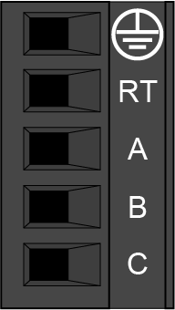
Table 2-6: Motor Power Output Mating Connector Ratings
| Specification | Description | |
|---|---|---|
| Type | 5-Pin Terminal Block | |
| Part Numbers | Aerotech: ECK02434 | |
| Phoenix: 1756311 | ||
|
Conductor Cross Section |
One conductor, stranded with ferrule and plastic sleeve | 14...22 AWG (0.25...2.5 mm2) |
| Two conductors (same cross-section), stranded , twin ferrule with plastic sleeve | 16...20 AWG (0.5...1.5 mm2) | |
| Tightening Torque | 0.5...0.6 N·m | |
| Conductor Insulation Strip Length | 7 mm (0.25 in) | |
|
(1) Refer to the manufacturer website for additional information. |
||