Safe Torque Off Input (STO)
The STO circuit is comprised of two identical channels, each of which must be energized in order for the
IMPORTANT: The drive might be equipped with an STO bypass circuit board. The bypass circuit board defeats the STO safety circuit and allows the system to run at all times. To use the STO safety functionality, remove the circuit board and make connections as outlined in this section.
IMPORTANT: The application circuit and its suitability for the desired safety level is the sole responsibility of the user of the drive.
WARNING: STO wires must be insulated to prevent short circuits between connector pins. The primary concern is a short circuit between STO 1 IN and STO 2 IN wire strands.
Table 2-25: STO Connector Pinout
|
Pin # |
Signal |
Description |
In/Out/Bi |
Connector |
|---|---|---|---|---|
|
1 |
Power Supply + |
Use only to defeat STO by connecting to STO 1 IN and STO 2 IN. Not for customer use. |
Output |
|
|
2 |
STO 1 IN |
STO Channel 1 Positive Input |
Input |
|
|
3 |
RETURN |
STO Negative Input |
Input | |
|
4 |
STO 2 IN |
STO Channel 2 Positive Input |
Input | |
|
5 |
Power Supply - |
Use only to defeat STO by connecting to RETURN. Not for customer use. |
Output |
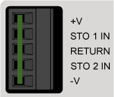
Table 2-26: STO Mating Connector Ratings
| Specification | Description | |
|---|---|---|
| Type | 5-Pin Terminal Block | |
| Part Numbers | Aerotech: ECK02393 | |
| Phoenix: 1827622 | ||
|
Conductor Cross Section |
One conductor, stranded with ferrule and plastic sleeve | 18...22 AWG (0.25...0.75 mm2) |
| Two conductors (same cross-section), stranded , twin ferrule with plastic sleeve | 20 AWG (0.5 mm2) | |
| Tightening Torque | 0.22...0.25 N·m | |
| Conductor Insulation Strip Length | 7 mm (0.25 in) | |
|
(1) Refer to the manufacturer website for additional information. |
||
Table 2-27: STO Electrical Specifications
|
Status |
Value |
|---|---|
| STO off (motion allowed) | 18-24 V, 7 ma |
|
STO on (safe state entered, no motion) |
0-6 V |
|
Recommended Wire Gauge |
22-26 AWG (0.5 - 0.14 mm2) |
|
STO System Power Supply |
PELV |
|
STO Wire Length (maximum) |
50 m |
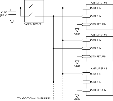
Typical STO Configuration shows one safety device connected to multiple drives in parallel.
WARNING: The drive does not check for short circuits on the external STO wiring. If this is not done by the external safety device, short circuits on the wiring must be excluded. Refer to EN ISO 13849-2. For Category 4 systems, the exclusion of short circuits is mandatory.
STO Standards
STO Standards describes and specifies the safety requirements at the system level for the Safe Torque Off (STO) feature of the drive. This assumes that diagnostic testing is performed according to STO Diagnostics and STO Standards Data.
|
Standard |
Maximum Achievable Safety |
|---|---|
| EN/IEC 61800-5- 2:2016 | SIL 3 |
| EN/IEC 61508-1:2010 | SIL 3 |
| EN/IEC 61508-2:2010 | SIL 3 |
| EN ISO 13849-1:2015 | Category 4, PL e |
|
EN/IEC 62061:2005 with Amendments |
SIL 3 |
Table 2-29: STO Standards Data
|
Standard |
Value |
|---|---|
| EN ISO 13849-1:2015 |
MTTFD > 100 years, DCAVG 99% Maximum PL e, Category 4 |
|
EN ISO 13849-1:2015 EN/IEC 61508 |
Lifetime = 20 years No proof test required Interval for manual STO test:
|
|
EN/IEC 61508 |
SIL3 PFH < 3 FIT SFF > 99% |
STO Functional Description
The motor can only be activated when voltage is applied to both STO 1 and STO 2 inputs. The STO state will be entered if power is removed from either the STO 1 or the STO 2 inputs. When the STO state is entered, the motor cannot generate torque or force and is therefore considered safe. Both STO channels must be driven at the same time. If they are not driven at the same time, a diagnostic test failure will occur (refer to STO Diagnostics).
The STO function is implemented with two redundant channels in order to meet stated performance and SIL levels. STO 1 disconnects the high side power amplifier transistors and STO 2 disconnects the low side power amplifier transistors. Disconnecting either set of transistors effectively prevents the drive from being able to produce motion.
The drive software monitors each STO channel and will generate an Emergency Stop software fault when either channel signals the stop state. Each STO channel contains a fixed delay which allows the drive to perform a controlled stop before the power amplifier transistors are turned off.
A typical configuration requiring a controlled stop has the Emergency Stop Fault mask bit set in the FaultMask, FaultMaskDecel, and FaultMaskDisable parameters. This stops the axis using the rate specified by the AbortDecelRate parameter. The software will disable the axis as soon as the deceleration ramp is complete. This is typically configured to occur before the STO channel turns off the power amplifier transistors.
The software-controlled stop functionality must be excluded when considering overall system safety. This is because the software is not safety rated and cannot be included as part of the safety function.
The software-controlled stop function can ignore short diagnostic pulses on the STO 1+ and STO 2+ inputs. The StoPulseFilter parameter specifies the maximum pulse width that the software will ignore. The filter parameter does not affect the operation of STO hardware channels.
To resume normal operation, apply power to both STO 1 and STO 2 inputs and use the Acknowledge All button or the AcknowledgeAll() or FaultAcknowledge() function to clear the Emergency Stop software fault. The recommended use of the Emergency Stop Fault fault mask bits prevent the system from automatically restarting.
You can achieve longer delay times through the use of an external delay timer, such as the Omron G9SA-321 Safety Relay Unit. Place this device between the system ESTOP wiring and the drive's STO inputs. Connect the ESTOP signal directly to a digital input, in addition to the external timer, to allow the drive to begin a software-controlled stop as soon as the ESTOP signal becomes active. Use the EmergencyStopFaultInput parameter to configure a digital input as an ESTOP input.
The STO feature can only be used with AC or stepper motor types. It is not certified to prevent hazardous motion when using DC brush or Voice Coil motor types.
Non-standard STO delay times are provided by special factory order. In this case, the non-standard STO delay time is indicated by a label placed on the slice amplifier’s main connector (STO DELAY = xx sec).
|
|
Value |
|---|---|
| STO Time Delay | 450-550 msec |
Table 2-31: Motor Function Relative to STO Input State
|
STO 1 |
STO 2 |
Motor Function |
|---|---|---|
| Unpowered | Unpowered | No force/torque |
| Unpowered (1) | Powered (1) | No force/torque |
| Powered (1) | Unpowered (1) | No force/torque |
| Powered | Powered |
Normal Operation |
|
1. This is considered a Fault Condition since STO 1 and STO 2 do not match. Refer to STO Diagnostics |
||
STO Startup Validation Testing
Verify the state of the STO 1 and STO 2 channels by manually activating the external STO hardware. Each STO channel must be tested separately in order to detect potential short circuits between the channels. The current state of the STO 1 and STO 2 inputs is shown in the Status Utility. A “–” indicates that the STO input is powered by a high voltage level (24 V). An “ON” indicates that the voltage source has been removed from the input (open circuit or 0 V), and that the STO channel is in the safe state.
DANGER: The STO circuit does not remove lethal voltage from the motor terminals. AC mains power must be removed before servicing.
STO Diagnostics
Activation of STO means removing power from the drive STO inputs. This is typically done by pressing the emergency stop switch. The drive initiates a diagnostic check every time the STO is activated after the Diagnostic Test Delay Time has elapsed. The diagnostic check verifies that each channel has entered the safe state. The drive is held in the safe state if it determines that one of the channels has not properly entered the safe state. An open circuit or short to 24 V in either STO channel will result in this condition (refer to STO Startup Validation Testing). The Status Utility screen can be used to verify the levels of the STO input signals while troubleshooting. The safe state is cleared when both STO channels are cycled with matching signal levels such that the diagnostic test completes successfully.
The drive is held in the safe state if it determines that one of the channels has not properly entered the safe state. In this case, the stoCrossCheckFault bit will be set and can be viewed in the STO Status status item. A Position Error Fault or Emergency Stop Fault will occur if motion is attempted while in this state. The drive will remain in the safe state until STO is reactivated with both channels in a safe state such that the diagnostics test completes successfully.
An open circuit or short to 24 V in either STO channel or a timing difference between the channels will result in a diagnostic test failure (refer to STO Startup Validation Testing). The Status Utility screen or STO Status status item can be used to verify the levels of the STO input signals while troubleshooting.
In order to pass internal testing, the STO circuit must be activated (power removed from both inputs) according to the interval specified in STO Standards Data.
|
Time |
Description |
Value |
|---|---|---|
| T1 | STO Delay Time (STO input active to motor power off) | 450-550 msec |
| T2 | STO deactivated to motor power on (the software is typically configured so that the motor does not automatically re-energize). | < 1 msec |
| T3 | Diagnostic Test Delay Time | 550-610 msec |
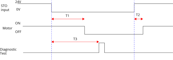
The software is typically configured to execute a controlled stop when the STO state is first detected. If power is reapplied to the STO inputs before the STO Delay Time, an STO hardware shutdown will not occur but a software stop may, depending on the width of the STO pulse. The controller will ignore STO active pulses shorter in length than the StoPulseFilter parameter setting.