Stepper Overview
A stepper motor can be an open or closed loop system. When it is a closed-loop system, Machine Setup configures the servo loop as a single feedback PI controller.
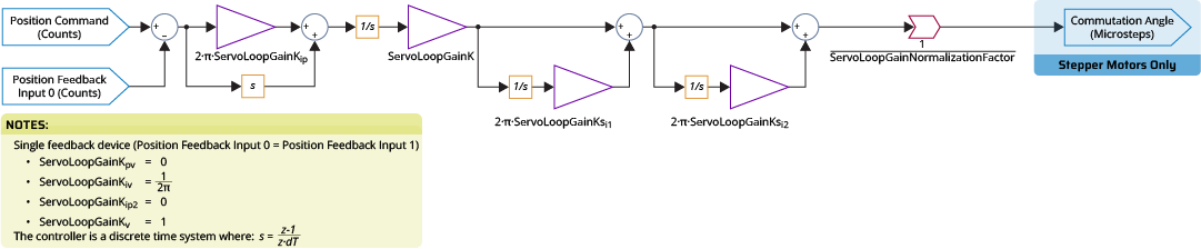
To configure the servo loop, use Machine Setup to set the servo gains that follow:
- ServoLoopGainKpv =

- ServoLoopGainKiv =

- ServoLoopGainKip2 =

- ServoLoopGainKv =

- ServoLoopGainKip =

- ServoLoopGainK =

- ServoLoopGainNormalizationFactor =

Servo Loop Tuning
To tune the servo loop for a stepper axis, use the Manual Servo Tuning tool in the Classical Tuning module in the Configure workspace.
Configuring Data Collection
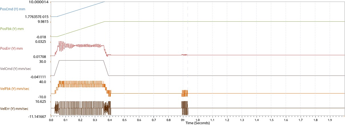
To tune the servo loop with the Manual Servo Tuning tool, first examine the behavior of your stepper axis from a plot collected during motion. The signals to plot include:
-
Position Command
-
Position Feedback
-
Position Error
-
Velocity Feedback
-
Current Command
Set the Data Collection Collection Period to the servo rate of the drive. Set the Time to Collect to the time it should take to complete one instance of the most aggressive move you are going to do. Refer to Configure Data Collection.
Setting Up Motion
Start the tuning process by defining the most aggressive target move you are going to do with the stepper. For tuning, the move should not be more than the MaxJogSpeed Parameter.
Tip: The execute command buttons can help when adjusting the motion parameters. When you set up the move that you want to benchmark, it can be easier to use repeated motion to quickly adjust servo parameters. Refer to Motion Functions.
Examining Results
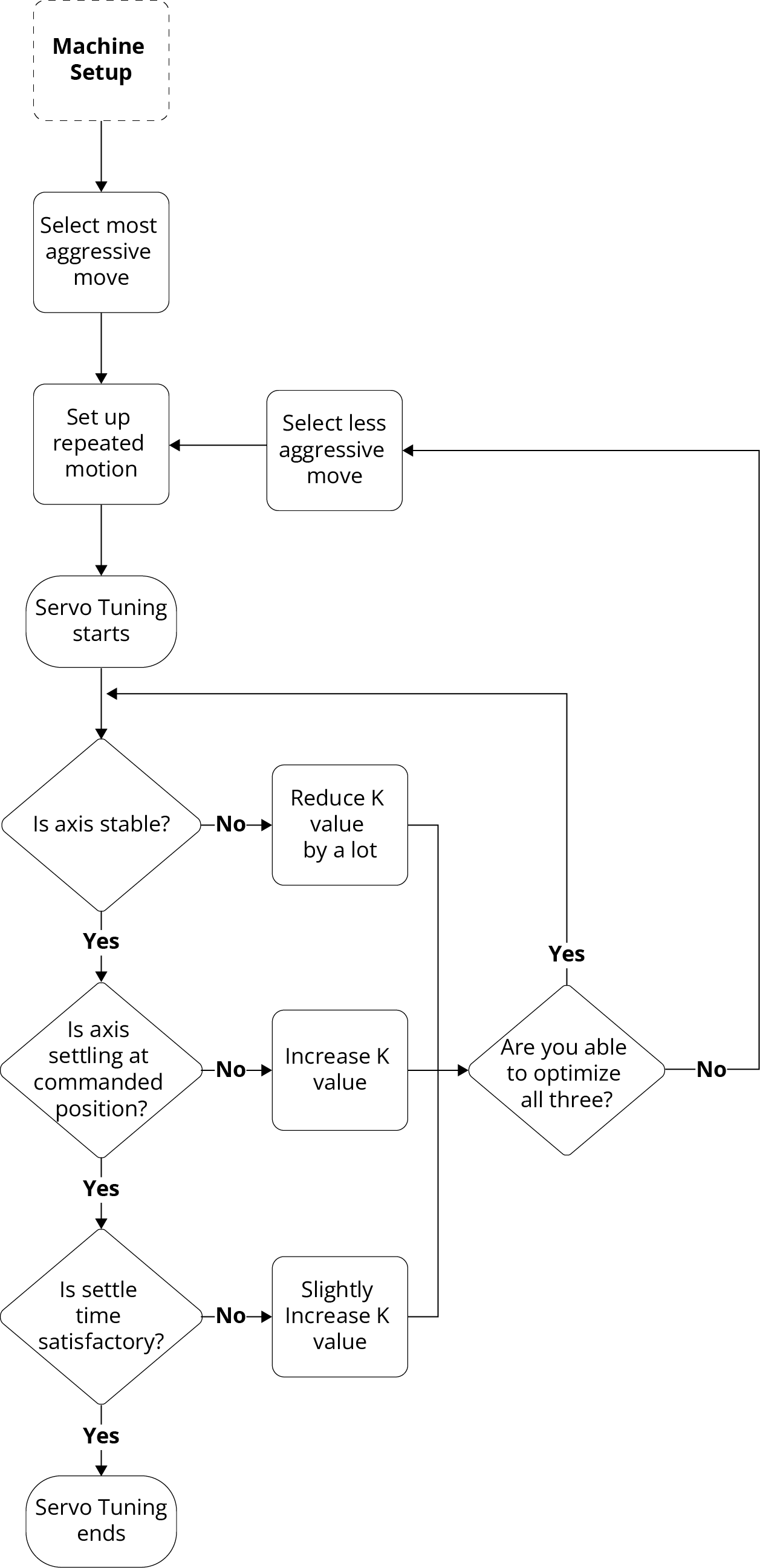
When tuning a stepper axis, optimize across these three values:
-
Maximize the accuracy of the position feedback at the end of a move compared to your original position command.
-
Minimize position error during travel.
-
Minimize the time necessary for the axis to settle at the end of a move.
Tip: Use Conditional Plotting and plot annotations to easily find when position error is higher than the acceptable limits and when velocity feedback is at a minimal value.
Adjusting Gains
For stepper axes, ServoLoopGainK Parameter and ServoLoopGainKiv Parameter have the same effect on the single-feedback PI controller. Thus, you only have to adjust the ServoLoopGainK parameter during the normal tuning process.
When you decrease the value of the ServoLoopGainK parameter, the axis is more stable, but the settle time increases, and the axis doesn't hold the commanded position at the end of a move. When you increase the value of this parameter, the axis is less stable with higher position error, but the settle time decreases, and the stepper can hold position at the end of a move.
After you collect and examine data from repeated snapshots do the procedure that follows.
- Manually adjust the K value from the toolbar.
- Apply the new parameter using the Apply button in the toolbar.
- Collect a new set of data from repeated snapshots.
When the adjusted gains are satisfactory, apply the final parameter values to the controller using the Save All button in the Configure workspace.
Tip: A stepper axis should always be stable when the ServoLoopGainK is equal to 0. If you cannot get your stepper axis to be stable during tuning, change the ServoLoopGainK parameter to 0 and collect more data. If the axis is still unstable, there is possibly a problem with your configured device or wiring.
Advanced Tuning
If you want minimal position error while commanding constant velocity motion, use the ServoLoopGainKsi1 Parameter. For minimal position error with constant acceleration, use the ServoLoopGainKsi1 Parameter and ServoLoopGainKsi2 Parameter.
WARNING: The ServoLoopGainKsi1 and ServoLoopGainKsi2 parameters decrease axis stability margins. They prevent the axis stability that is usually given when the ServoLoopGainK parameter has value of 0. When adjusting these parameters, make sure that the axis is not near any limits or crash conditions.
When you set these parameters for stepper axes, start with a ServoLoopGainKsi1 value of half the crossover frequency. Always set the ServoLoopGainKsi2 parameter to half of the ServoLoopGainKsi1 value. Refer to the Servo Tuning guide for more information.


