Over Current Fault

An OverCurrentFault occurs when the average motor current is more than the value specified in the AverageCurrentThreshold Parameter and the AverageCurrentTime Parameter.

For an OverCurrentFault to occur, the axis must be enabled, and the OverCurrentFault box must be selected in the FaultMask Parameter. Because the OverCurrentFault helps prevent high currents from damaging your equipment, Aerotech recommends that the OverCurrentFault is enabled at all times.

Table: OverCurrentFault Causes and Solutions

Cause Examine Your System Solution

Servo Tuning

The servo is unstable and goes into a fault condition when the stage is enabled or trying to move. When this occurs, there is usually a noise or sudden movement.

  • Use EasyTune in the Servo module of the Configure workspace to set the servo gains.

  • Use Open Loop Tuning to find stable gains for your system.

  • Refer to the Servo Topic section on the Axes Category page for more help with setting up the servo loop.

  • Do a check for mechanical restrictions or changes to mechanical parts that possibly can change system mass and stiffness.

Mechanical Restriction

  • Position feedback does not keep up with the position command.

  • The fault occurs several seconds after the axis is enabled or the axis starts to move unexpectedly.

  • Make sure that the red shipping brackets were removed from the stage.

  • Make sure that external parts, such as cables, are not causing an interference with the stage or are applying force in the direction of travel.

  • If you have a pneumatic counterbalance, make sure that air supply is connected and the pressure is set correctly.

  • If you have an air bearing stage, make sure that the air supply is connected and pressure is set correctly.

  • Changes to the mechanical components can cause changes to the system stiffness. When this occurs, you must update the servo loop.

System Capability

The fault occurs during a fast sequence of moves or continuous moves.

  • Decrease the speed of the move command.

  • Decrease the machine duty cycle.

Electrical Wiring or Configuration Incorrect

  • Too much current is necessary for holding a position or for moving.

  • Feedback moves in the opposite direction of the command.

  • Stage encounters a hardstop during a homing cycle.

  • Do a check for electrical damage.

  • Make sure that all cables are connected to the correct device as identified in Machine Setup.

  • Use the Motor Phasing module to find problems with motor wiring.

  • Look at the setting for CommutationInitializationSetup Parameter.

  • If applicable, make sure that the CurrentCommandCouplingFollowerDirection Parameter is set to the correct polarity.

  • Go through Machine Setup again, and make sure the correct electrical and mechanical devices are shown. Make sure that the bus voltage is set correctly on the electrical device.

  • Make sure that the feedback and wiring orientation are the same, and if not, invert feedback.

  • If you are encountering a hard stop during the homing cycle, make sure that homing settings are correct.

Mechanical Component Failure

  • Brake does not disengage when the stage is enabled.

  • Bearings sound or feel rough.

  • Do a check for mechanical damage.

  • If the stage has a brake, make sure that the BrakeOutput Parameter and BrakeSetup Parameter are set correctly.

  • Make sure that the power supply for the brake works and is wired correctly.

  • Make sure that the bearings are lubricated as shown in the hardware manual.

  • Examine the stage for signs of rubbing or for signs that it is becoming worn.

  • Changes to the mechanical components can cause changes to the system stiffness. When this occurs, you must update the servo loop.

Parameter or Calibration File Settings

  • The stage faults during a move that it should be able to make.

  • The fault occurs during a fast move after a short amount of time.

  • Look at the settings for the AverageCurrentTime Parameter.  This parameter usually is set to a conservative value at the factory but can be increased to be more near to the thermal time constant of the system.  If necessary, use the Global Technical Support Portal to contact Aerotech Global Technical Support.

  • Look at the calibration file for large changes in calibration over short distances.  This can cause an unexpected amount of current draw.

  • Look at the Autofocus parameters if applicable.

  • Go through Machine Setup again, and make sure the correct electrical and mechanical devices are shown.

  • Make sure that the limit/homing settings are correct. Make sure that the limit type (limit switch or current threshold) is correct.

  • Make sure parameter file counts per unit are the same as the motor counts.

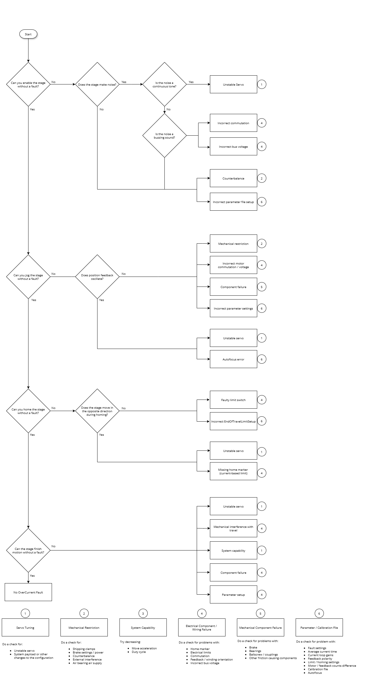
Use the chart in the drop-down that follows to help you find the cause of the fault.