Configure Automation1 for EtherCAT
Optional Purchase Necessary: This feature is available only if you purchased the Industrial Ethernet (-IE2) license option. Contact your Aerotech sales representative to speak about your licensing needs.
IMPORTANT: EtherCAT is supported only on drive-based controllers.
You can use the Automation1 EtherCAT slave device with any third-party EtherCAT master device. The procedures that follow show how to configure an EtherCAT network when you use Automation1 and TwinCAT3.
Configure EtherCAT Mappings
To enable EtherCAT, you must first specify an EtherCAT mapping on the Automation1 controller. To do this, use the procedure in the drop-down that follows.
-
Open Automation1 Studio and go to the Develop workspace.
-
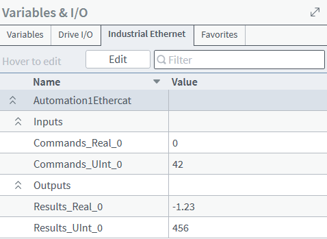
In the right pane, open the Variables & I/O module, and select the Industrial Ethernet tab. For more information about this tab, see Industrial Ethernet Tab.
-
Click the Edit button.
-
Click the + Connection button to create a new Industrial Ethernet connection.
-
Enter a name for the connection and make sure that the protocol is set to EtherCAT.
-
Click the Add button.
-
After you add the connection, expand the drop-down arrows and click the + button to add two inputs and two outputs.

-
After you add the inputs and outputs, click Save to apply the configuration. This resets the controller. When you start the controller with an EtherCAT configuration, the controller brings up the EtherCAT communication stack.
TwinCAT Overview
The Windows Control and Automation Technology (TwinCAT) is a real-time automation control software suite and an industry standard for the TwinCAT communication protocol. TwinCAT runs on the Windows operating system and uses Visual Studio for its front-end.
TwinCAT has two packages, the XAE and XAR:
- eXtended Automation Engineering (XAE): SDK for building and developing TwinCAT applications
- eXtended Automation Runtime (XAR): Real-time system environment
System Requirements for TwinCAT
Your system must have the specifications that follow to use TwinCAT.
Dedicated Network Adapter
-
EtherCAT must have its own network adapter. It cannot use the same network adapters that are connected to your company network or to the Internet.
-
Most standard Ethernet Network Interface Cards (NICs) are supported. For a full list, go to the Beckhoff Information System site.
Real-Time Performance
-
The PC that runs TwinCAT must not have a real-time operating system such as TenAsys INtime. If your PC needs to run a real-time operating system, you must run TwinCAT on a different PC.
Virtualization Settings
-
TwinCAT must have the VT-x CPU BIOS setting.
-
TwinCAT cannot run in Hyper-V environments.
Visual Studio
-
TwinCAT is built as an extension to Microsoft Visual Studio. To install Visual Studio from Microsoft, go to the Microsoft Visual Studio download page. TwinCAT supports Visual Studio 2013-2019. Aerotech uses Visual Studio 2019.
-
For the installation workload options, select Desktop development with C++. If you are going to use TwinCAT with a language other than English, you must install that language and select it in Visual Studio before you install TwinCAT.
-
Go to the Beckhoff software page for the TwinCAT software download.
-
Download the .
zipfile that is in the eXtended Automation Engineering (XAE) section. This download includes a full setup installer. -
Extract the
.zipfile and run the installer. -
Install the XAR and XAE environments.
TwinCAT Network Adapter Configuration
The TwinCAT PC must have a dedicated NIC to run the EtherCAT network. This can be an on-board NIC integrated into the PC motherboard or on an expansion card with the PCIe.
To create an EtherCAT network, use an Ethernet cable to connect the Industrial Ethernet RJ-45 port A of the Automation1 controller to the TwinCAT PC NIC. To add devices to the EtherCAT network, connect them to the Industrial Ethernet RJ-45 port B.
-
Launch Visual Studio with TwinCAT.
-
Go to Extensions -> TwinCAT-> Show Realtime Ethernet Compatible Devices to see the available TwinCAT RT adapters.
-
The Compatible Devices dialog shows the devices that are installed and supported. Most standard Ethernet NICs are supported. To see all of the supported Ethernet NICs, visit the Beckhoff Information System site.
-
Click on the Ethernet adapter that you want to use, and click the Install button to install the Beckhoff RT Ethernet driver.
-
This device now shows in Installed and ready to use devices (realtime capable). You will use this network adapter for EtherCAT communication in later steps.
-
Exit the Installation of TwinCAT RT-Ethernet Adapters dialog.
You must add the ESI file to the TwinCAT dictionary so that it recognizes the Automation1 EtherCAT slave device. To do this, use the procedure that follows. The TwinCAT version used in these instructions is 3.1.
-
Find the
Automation1EtherCAT.xmlESI file in the Automation1 install directory:{Automation1_Install_Dir}\EtherCAT\Automation1EtherCAT.xml -
Copy this file to the TwinCAT device dictionary:
{TwinCAT_Install_Dir}\{VersionNumber}\Config\Io\EtherCAT.
-
Open Visual Studio with TwinCAT and select Create a new project.
-
In the search bar enter "Twincat" and select the TwinCAT XAE Project.
-
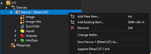
When the project is open, right click on the I/O -> Devices icon in the Solution Explorer and select Add New Item….
-
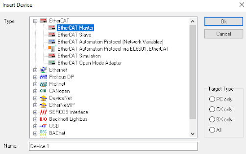
On the Insert Device dialog that comes into view, double-click on EtherCAT Master.
-
In the Solution Explorer, double-click the EtherCAT Master device that was added in the previous step. Go to the Adapter tab that is in the opened menu.
-
Select the NIC driver that you installed in the TwinCAT Network Adapter Configuration section. You may have to restart your PC after you install the NIC driver.
-
In the Solution Explorer, right click on the EtherCAT Master that you added and select Add New Item….
-
In the Insert EtherCAT Device dialog, select the Automation1 slave device. If you do not see it in the dialog menu, make sure that you copied the ESI file to the TwinCAT3 device dictionary. Refer to the How to configure Automation1 for TwinCAT section.
Do a Check for Real-time Data Transfer
The procedures that follow include instructions to make sure that Rx and Tx PDO data transfer works correctly.
To make sure that there is incoming real-time PDO data transfer, you must set the RxPDO value of the controller from TwinCAT for the associated mapping. Use the procedure that follows.
-
On the top title bar, select Extensions -> TwinCAT -> Restart TwinCAT (Config Mode).
-
Click OK for all of the dialogs that come into view. When asked to restart in Free Run, select yes.
-
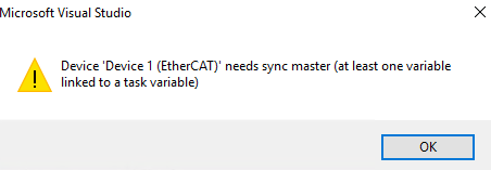
If you get a warning that says the master must have a linked variable, you can safely ignore it for this test.
-
-
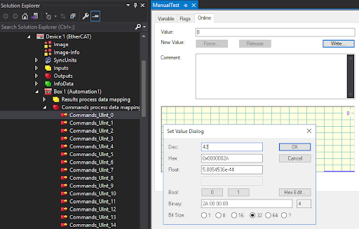
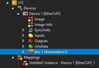
For the first mapped integer, double-click the I/O -> Devices -> Device X (EtherCAT) -> Box Y (Automation1) -> Commands process data mapping -> Commands_UInt_0.
-
Select the Online tab and click the Write button to set a new value in the Set Value dialog.
-
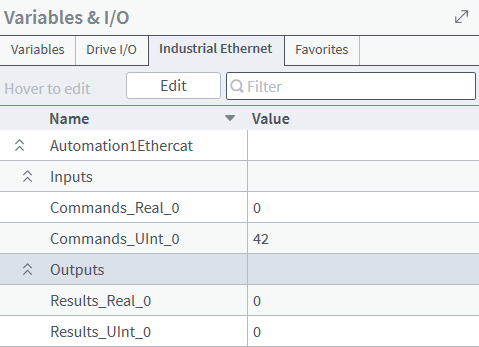
Make sure that this new value comes into view in the Variables & I/O module -> Industrial Ethernet tab of the Develop workspace. For more information about this tab, see Industrial Ethernet Tab.
IMPORTANT: If you did not do the RxPDO test, you must restart your system. You can start at step 3 if the system is already running in Free Run mode.
To make sure there is outgoing real-time PDO data transfer, you must set the Tx PDO value of the controller from Automation1 for the associated mapping. Use the procedure that follows.
-
On the top title bar, select Extensions -> TwinCAT -> Restart TwinCAT (Config Mode).
-
Click OK for all the dialogs that come into view. When prompted to restart in Free Run, select yes.
-
If you get a warning that says the master requires a linked variable, you can safely ignore it for this test.
-
-
Use the edit icon in the Variables & I/O module ->Industrial Ethernet tab of the Develop workspace to look at the associated output value. For more information about this tab, see Industrial Ethernet Tab.
-
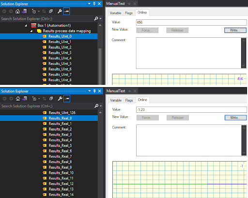
Confirm that the new value is sent to TwinCAT. Double-click I/O -> Devices -> Device X (EtherCAT) -> Box Y (Automation1) -> Results process data mapping -> Results_UInt_0. Use the Online tab to view the value.
TwinCAT3 Advanced PLC Example
The procedures that follow show you how to create and run a sample PLC project within TwinCAT3. This sample project uses a PLC function to generate a sawtooth wave from TwinCAT and output it to the first RxPDO real on Automation1.
-
In the Solution Explorer, right click on the PLC heading and select Add new item…
-
In Plc Templates, select the Standard PLC Project, set the name field to "ExamplePlc", and click Add.
-
The system automatically creates a MAIN program, but it needs a function to call.
-
-
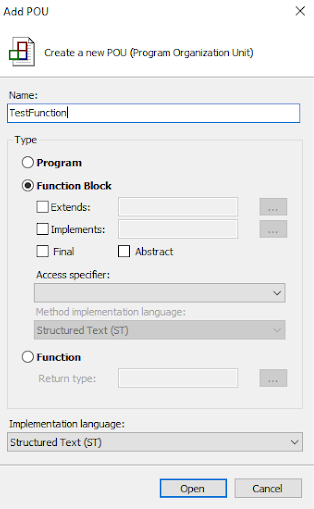
Right click on POUs and select Add POU.
-
In the dialog that comes into view, set the name to TestFunction and change the Implementation Language to Structured Text. Click Open.
-
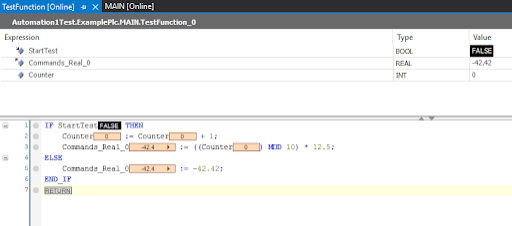
For the new TestFunction replace the autogenerated code with the code that follows. To edit the code, double-click on TestFunction and use the variable window on the top half of the editor. This code declares the variables for the function.
FUNCTION_BLOCK TestFunction VAR_INPUT StartTest: BOOL := FALSE; END_VAR VAR_OUTPUT Commands_Real_0: REAL := 0.0; END_VAR VAR Counter: INT := 0; END_VAR -
Enter the code that follows in the bottom half of the editor to define the behavior of the function. This algorithm generates a sawtooth wave when
StartTestis True. If it is not true, a constant value is generated.IF StartTest THEN Counter := Counter + 1; Commands_Real_0:= ((Counter) MOD 10) * 12.5; ELSE Commands_Real_0:= -42.42; END_IF -
Save the changes to the TestFunction.
-
Double-click on the MAIN program and replace the autogenerated code in the top editor with the code that follows. This declares the variables for the program.
PROGRAM MAIN VAR StartTest AT %I* : BOOL; Commands_Real_0 AT %Q* : LREAL; TestFunction_0 : TestFunction; END_VAR -
Enter the code that follows in the bottom half of the editor to define the behavior of the main program. This code calls the TestFunction of each iteration.
TestFunction_0(StartTest := Main.StartTest, Commands_Real_0 =>
Main.Commands_Real_0);
-
Save the changes to the MAIN program.
-
Build the project. You will get the warning that follows, but the build should succeed.
-
In the Solution Explorer, expand the ExamplePlc Instance.
-
Under the PlcTask Outputs, right click on MAIN.Commands_Real_0, and click Change Link….
-
In the dialog that comes into view, select the Commands_Real_0 data item in the Automation1 device drop-down.
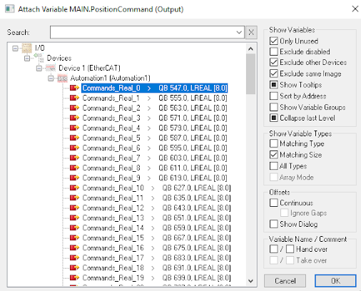
-
Select OK to close the dialog.
-
Save and rebuild. The build should succeed without warnings.
-
On the top title bar, select Extensions -> TwinCAT -> Activate Configuration.
-
Click through the two dialogs to start the EtherCAT master. If you did not yet input your license for TwinCAT 3, you will be prompted to do so.
-
On the top title bar, select Extensions -> PLC -> Login. Then select Extensions -> PLC -> Start. This loads the MAIN program we wrote in How to build a sample PLC project.
-
In the PLC node in the Solution Explorer, double-click on the TestFunction. The debug displays should show StartTest as "FALSE" and Commands_Real_0 as "-42.42".
-
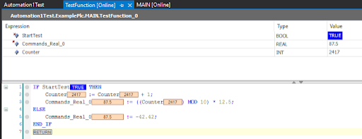
To start the sawtooth wave generation, right click on MAIN.StartTest in ExamplePlc Instance -> PlcTaskInputs and select Online write ‘1’.
-
Navigate back to the TestFunction. The debug windows should now show StartTest as "TRUE" and the Commands_Real_0 changing over time with the sawtooth wave.
To verify that the sawtooth wave generated by the PLC is received by the Automation1 controller, use Data Collection with the AeroScript mappings you configured on the controller (see Configure EtherCAT Mappings on this page).
-
Open Automation1 Studio and navigate to the Visualize workspace.
-
Click the Configure Signals button and add the EtherCAT Rx Pdo signal with the Data Info set to 25166080. This value is calculated from the
computeEthercatAdditionalData()AeroScript function, which is described in the EtherCAT Status Items and Data Collection section of the EtherCAT Overview page.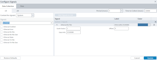
-
Click the Update button.
-
To start Data Collection, click the Collect Snapshot button.
-
Verify that the EtherCAT Rx signal shows the sawtooth wave.
EtherCAT Distributed Clocks
The EtherCAT slave protocol of the Automation1 controller supports distributed clocks. The procedures that follow show how to configure an EtherCAT network using distributed clocks when you use Automation1 and TwinCAT3. These procedures allow HyperWire communication to be externally synchronized to other devices on the EtherCAT network. This guarantees the round-trip latency between TwinCAT3 and the Automation1 controller.
-
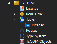
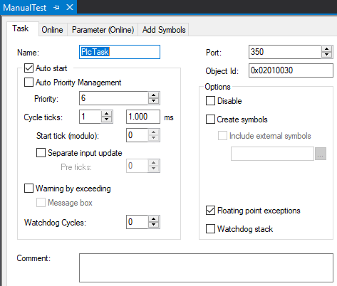
Double-click SYSTEM -> Tasks -> PlcTask.
-
Select the Task tab and change the Cycle ticks to 1.
-
Double-click I/O -> Devices -> Device X (EtherCAT) -> Box Y (Automation1)
-
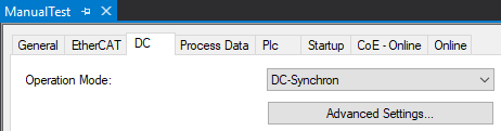
Select the DC tab and click the Advanced Settings... button.
-
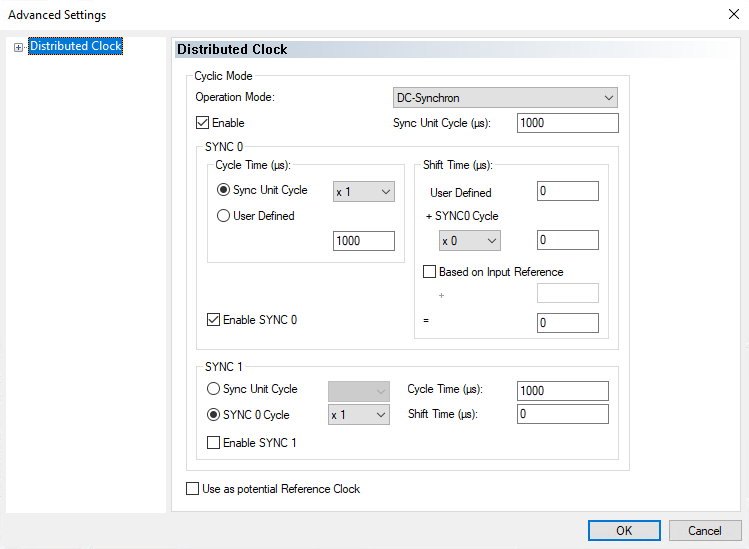
Change the Operation Mode to DC-Synchron and enable the Enable checkbox in the Advanced Settings dialog.
-
On the top title bar, select Extensions -> TwinCAT -> Activate Configuration.
-
Click OK for all the dialogs that come into view. When prompted to restart in Run Mode, select OK.
Configure Automation1 for EtherCAT Distributed Clocks
Open Automation1 Studio and use Machine Setup to configure your controller to use HyperWire communication. Configure HyperWire External Synchronization to use the EthercatSync0 signal and the frequency that you specified when configuring TwinCAT3 to operate using distributed clocks. Refer to Machine Setup for more information.
Troubleshooting EtherCAT Distributed Clocks in Automation1
Automation1 supplies some HyperWire external signal synchronization status items that you can use directly or through Data Collection. All of the HyperWire external synchronization status items are in the System category. You can access the HyperWire external synchronization status items with the StatusGetSystemItem() function. You can add the HyperWire external synchronization status items to Data Collection with the DataCollectionAddSystemSignal() function.
To get status information for HyperWire external synchronization while using EtherCAT distributed clocks, use the status items that follow.
-
HyperWire External Synchronization Active
-
HyperWire External Synchronization Frequency
-
HyperWire External Synchronization Lagging
-
HyperWire External Synchronization Adjustment Nanoseconds
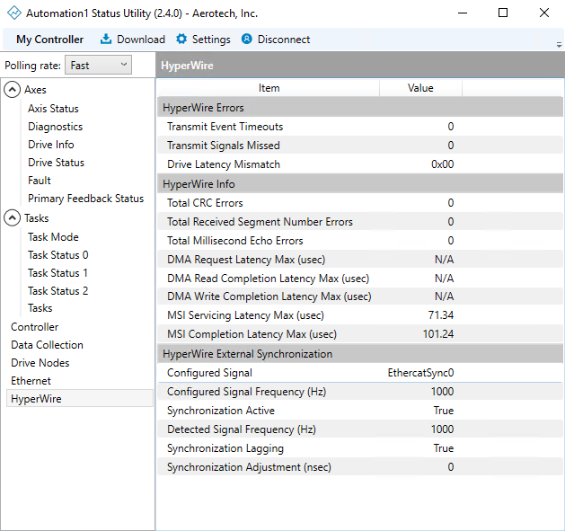
As an alternative to using status items, refer to the HyperWire tab of the Automation1 Status Utility. The HyperWire External Synchronization section shows the information that follows.
Table: HyperWire External Synchronization
|
HyperWire External Synchronization Item |
Description |
|---|---|
|
Configured Signal |
Shows the configured external signal with which HyperWire will be synchronized. |
|
Configured Signal Frequency |
Shows the configured frequency of the external signal with which HyperWire will be synchronized in Hertz. |
|
Synchronization Active |
Shows whether HyperWire is actively synchronized to an external signal. |
|
Detected Signal Frequency |
Shows the detected frequency of the HyperWire external synchronization signal in Hertz. |
|
Synchronization Lagging |
Shows whether the HyperWire internal synchronization signal is lagging behind the external synchronization signal. |
|
Synchronization Adjustment |
Shows the calculated adjustment between the HyperWire internal synchronization signal and the external synchronization signal in nanoseconds. |
Troubleshooting on Your Drive-Based Controller
If you are unable to communicate between Automation1 and TwinCAT, confirm the conditions that follow on your Automation1 drive-based controller.
-
The Industrial Ethernet cable from the master is plugged into the EtherCAT Input port.
-
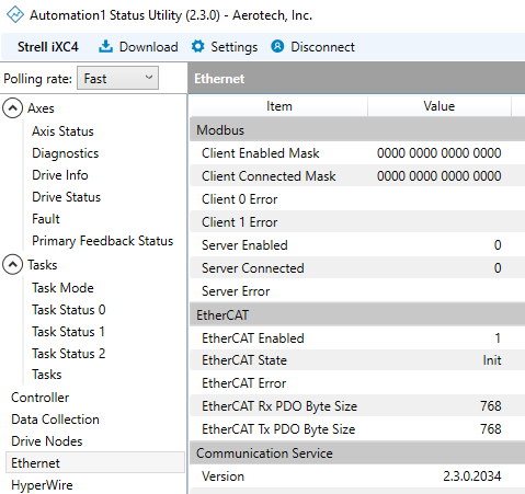
The Automation1 controller has EtherCAT mappings configured and the controller is running through the Status Utility. The Ethernet tab shows the EtherCAT information that follows.
| EtherCAT Item | Description |
|---|---|
|
EtherCAT Enabled |
Shows if the EtherCAT slave is configured in the aeroscriptmappings file. |
|
EtherCAT State |
Shows the current state of the EtherCAT slave. The Init, SafeOp, PreOp, and Op states are supported. This item will display “Off” if EtherCAT enabled is False. |
|
EtherCAT Connection Error |
Shows the active connection error on the EtherCAT slave, if any. |
|
EtherCAT RxPDO Byte Size |
Displays the current RxPDO size of the EtherCAT slave in bytes. |
|
EtherCAT TxPDO Byte Size |
Displays the current TxPDO size of the EtherCAT slave in bytes. |
Tip: If Automation1 encounters
Troubleshooting from TwinCAT
From TwinCAT, if the Automation1 device cannot be found, confirm the conditions that follow.
-
The EtherCAT network hardware is properly configured for the EtherCAT master.
-
There is a valid Ethernet connection between the Automation1 controller and the TwinCAT PC.
-
The Automation1 ESI file has been set correctly on the master. See the How to configure Automation1 for TwinCAT section for instructions.


