EtherCAT Overview
Optional Purchase Necessary: This feature is available only if you purchased the Industrial Ethernet (-IE2) license option. Contact your Aerotech sales representative to speak about your licensing needs.
IMPORTANT: EtherCAT is supported only on drive-based controllers.
The Automation1 controller supports the EtherCAT slave protocol.
EtherCAT-Related Terms
The list that follows includes terms and definitions related to EtherCAT:
- Ethernet for Control Automation Technology (EtherCAT): A real-time communication protocol over standard Ethernet hardware / networks.
- Master / Slave: In EtherCAT, the network topology has one master controller that communicates with up to N (65,535) slave controllers. The maximum number of slave devices is limited by bandwidth
 A measurement of the capacity of a network to transmit data. Typically expressed in bits-per-second or bytes-per-second. restrictions.
 - The Windows Control and Automation Technology (TwinCAT): This platform is an EtherCAT master controller.
- The EtherCAT Slave Information (ESI): file defines the capabilities of the EtherCAT slave device. This file is imported by the EtherCAT master software when you configure the EtherCAT network.
- Process Data Objects (PDO) make up the real-time application data transfer protocol over the network. The ESI file specifies the layout of data in the PDO space. The two different PDO types are as follows:
- RxPDO: data received from the master device by the slave device.
- TxPDO: data sent to the master device from the slave device.
EtherCAT ESI Definition File
The EtherCAT Slave Information (ESI) definition file is named Automation1EtherCAT.xml. The EtherCAT master imports the ESI file, which specifies the object dictionary of the Automation1 controller and the layout of data in the PDO space.
IMPORTANT: The Rx and Tx PDO spaces each have 64 32-bit unsigned integers with 64 64-bit double-precision floats. The floats follow the integers in the memory. Thus, the integers start at byte offset 0, and the reals start at offset 256.
Table: EtherCAT ESI Definition File
| PDO | UInt32 | Float64 |
|---|---|---|
| Rx | Commands_UInt[64] | Commands_Real[64] |
| Tx | Results_UInt[64] | Results_Real[64] |
Controller Data Layout
Data Access
Automation1 uses Industrial Ethernet mappings to expose the PDO space of EtherCAT. These Industrial Ethernet mappings connect the memory areas of the EtherCAT data to random controller data types. The table that follows shows the access level of the registers.
Table: Register Access
| EtherCAT | Access |
|---|---|
| RxPDO | Read-Only |
| TxPDO | Read/Write |
You can configure the fields that follow for each Industrial Ethernet mapping:
- Name: The name of the variable. The controller automatically converts the name into an AeroScript variable. You can then use it in programs or libraries.
- Count: The count specifies the number of sequences there are of this variable. With counts of more than 1, the controller accesses the variables like an array. You can access the variables through an Industrial Ethernet mapping array.
- Type: The type lets you configure EtherCAT data as different data types. The supported data types are in the table that follows.
Table: Supported Data Types
Data Type Description UInt8 8-bit unsigned integer UInt16 16-bit unsigned integer UInt32 32-bit unsigned integer Int8 8-bit signed integer Int16 16-bit signed integer Int32 32-bit signed integer Float32 32-bit single-precision floating-point value Float64 64-bit double-precision floating-point value - The address range for integer variables starts at byte address 0. For integer variables, Aerotech recommends that you select the UInt32 data type so that it is the same as the ESI definition file.
- The address range for real variables starts at byte address 256. For real variables, Aerotech recommends that you select the Float64 data type so that it is the same as the ESI definition file.
- Byte Address: This configures the byte offset of the register.
- Bit Address: This configures the bit offset of the register.
- The final address is the sum of byteAddress * 8 + bitAddress.
- Non-bit data types must be 8-bit byte aligned.
- Comment: You can add a comment about the mapping.
In Automation1 Studio, you can configure the Industrial Ethernet mappings with the Industrial Ethernet Configuration dialog. This is in the Industrial Ethernet tab in the Variables & I/O module of the Develop workspace. For instructions on how to do this, use the Help procedures in the Industrial Ethernet Tab section of the Variables & I/O Module page. Refer to the sections that follow for examples.
Industrial Ethernet Mappings Example
After you configure the Industrial Ethernet mappings, the controller automatically converts the information into AeroScript properties that you can edit.

The code that follows is an example of the AeroScript properties after mapping.
property $Commands_Real_0 as real
property $Commands_UInt[$index as integer] as integer
property $Results_Real[$index as integer] as real
property $Results_UInt_0 as integer
To configure EtherCAT mappings, go to the Configure EtherCAT Mappings section of the Configure Automation1 for EtherCAT page.
EtherCAT Status Items and Data Collection
Automation1 supplies EtherCAT status items that you can use directly or through Data Collection. All of the EtherCAT status items are in the System category. You can access the EtherCAT status items with the StatusGetSystemItem() function. You can add the EtherCAT status items to Data Collection with the DataCollectionAddSystemSignal() function.
Tip: If Automation1 encounters
To get status information for the client and the server configurations, use these status items:
- Ethercat Connected
- Ethercat Error
To get the total size in bytes of the PDO data for Rx and Tx channels, use these status items:
- Ethercat Rx Pdo Size
- Ethercat Tx Pdo Size
To get the data that is sent over the EtherCAT connection, use these status items:
- Ethercat Rx Pdo
- Ethercat Tx Pdo
The Ethercat Rx Pdo status item and the Ethercat Tx Pdo status item must have one more data field to specify the connection index, data type, byte offset, and bit offset. To determine the correct additional data value, use the computeEthercatAdditionalData() function. If you want to use this function, you must add the code to your AeroScript program. The list that follows includes the variables for the computeEthercatAdditionalData() function. The example program shows you how to use this function.
- $Index – The index of the connection as defined in Automation1. The first created connection is index 0. To see the currently defined connections, go to the Variables & I/O module in the Develop workspace and open the Industrial Ethernet tab. For more information about this tab, see Industrial Ethernet Tab.
- $DataType – The type of the data.
- $BitOffset – The bit offset of the data item as defined in the EtherCAT mapping.
- $ByteOffset – The byte offset of the data item as defined in the EtherCAT mapping.
function computeEthercatAdditionalData($Index as integer, $DataType as EthercatRegisterDataType, $BitOffset as integer, $ByteOffset as integer) as integer
     var $additionalData as integer

     $additionalData = ($Index << 28) & 0xF0000000 | ($DataType << 23) & 0x0F800000 |($BitOffset << 20) & 0x00700000 | ($ByteOffset & 0x000FFFFF)

     return $additionalData
end

program
     $iglobal[0] = computeEthercatAdditionalData(0, EthercatRegisterDataType.Float64, 0, 256)
end
Networking
EtherCAT networks are built with standard Ethernet RJ45 hardware that run full-duplex Ethernet physical layers. Because of this, you can implement real-time communication networks with commercial networking hardware.
EtherCAT controllers have one or two Ethernet interfaces and usually have a ring-based topology. Data flows from the master device to each of the interconnected slave devices and then back to the master device in a ring, making two daisy chain networks. The network is redundant, so if one of the links is removed or changes, data still flows through the hardware as expected.
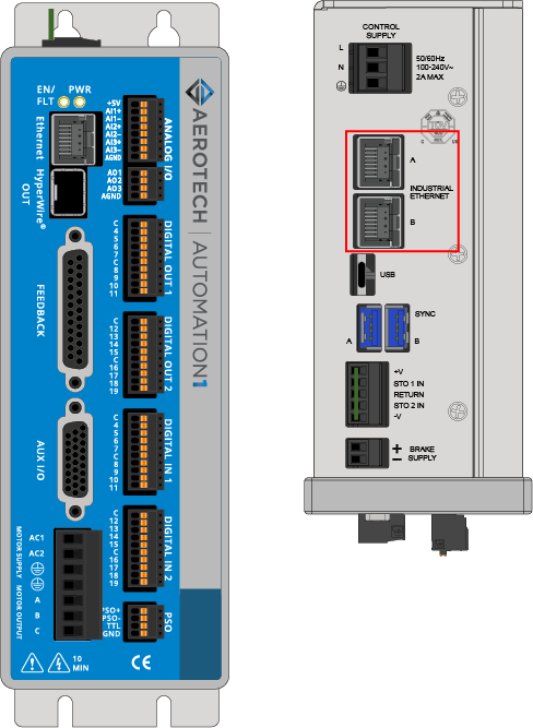
The Automation1 controller has two Industrial Ethernet ports labeled A and B. For EtherCAT, port A is the input port and port B is the output port. Use port A to connect the controller to the EtherCAT network. Port B is optional, and you can use it to connect to more EtherCAT devices on the same network.
Bandwidth
The Automation1 controller hardware has 100BASE-TX, which can communicate at 100 Mbps. An EtherCAT network that uses 100BASE-TX can send a maximum of 12,080 bytes if it stays at a 1 ms update rate.
The Automation1 EtherCAT ESI definition uses 64 32-bit unsigned integers and 64 64-bit floats. This PDO space uses 768 bytes, which is approximately 6% of 1 ms bandwidth![]() A measurement of the capacity of a network to transmit data. Typically expressed in bits-per-second or bytes-per-second..
A measurement of the capacity of a network to transmit data. Typically expressed in bits-per-second or bytes-per-second..
Licensing
The Industrial Ethernet (-IE) licensing option of Automation1 supports these EtherCAT stacks on the controller:
- -IE1: No EtherCAT support
- -IE2: EtherCAT support
- -IE3: No EtherCAT support
Troubleshooting
Use the Status Utility to make sure that an EtherCAT slave is configured and running. The Ethernet tab shows the EtherCAT information.
Table: EtherCAT Items in Status Utility
| EtherCAT Item | Description |
|---|---|
| EtherCAT Enabled | Shows if the Industrial Ethernet mappings contain an EtherCAT slave configuration |
| EtherCAT State | Shows the current state of the EtherCAT slave |
| EtherCAT Connection Error | Shows the active connection error on the EtherCAT slave, if there is one |
| EtherCAT RxPDO Size | Number of bytes configured for data coming to Automation1 from the master using the RxPDO |
| EtherCAT TxPDO Size | Number of bytes configured for data going from Automation1 from the master using the TxPDO |


