Axis Calibration
Axis calibration corrects the position of an axis based on the position of one or two reference axes and the values that you specify in a calibration table. To edit the calibration configuration in Studio, in the Configure workspace, under the Controller category, select the Calibration Topic. You can also load calibration without resetting the controller by using the CalibrationLoad() function. For more information, refer to Calibration Functions.
A calibration file includes one or more calibration tables that do the same type of calibration. Calibration files must use the UTF-8 encoding. A calibration table includes the calibration data (correction values) for one or two axes. A calibration table can be a 1D axis calibration table, a 2D axis calibration table, or a galvo 2D axis calibration table.
Axis calibration is additive. Each calibration table supplies a correction value for an axis independently of all other calibration tables, and the final correction value is the sum of all other correction values.
If the position of the reference axes is equal to the reference position of a calibration table entry, the correction value for that table entry is used as the active correction value. But, if the position of the reference axes is between two reference positions in the table, linear interpolation is used to find a correction value between the two correction values in the table. Finally, if the position of the reference axis is not within the values in the table (all positions in the table are either greater or less than the position of the reference axis), the nearest end point of the table is used to calculate the correction value.
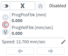
An active C on the axis dashboard indicates that the axis positions will be corrected.
IMPORTANT: All calibration tables follow the sign of the encoder. The ReverseMotionDirection Parameter has no effect on calibration values such as sample distances and correction.
1D Axis Calibration
IMPORTANT: Axis indices are usually specified as zero-based integers. But calibration files specify axis indices as one-based integers.
IMPORTANT: All corrections are bidirectional, which means that the correction value applied for a given position of the reference axis is the same regardless of the sign or value of its velocity.
Use 1D axis calibration to correct the position of an axis based on the position of another axis. You can use 1D axis calibration for accuracy correction, orthogonality correction, straightness correction, or ThermoComp. Axes must be homed before they are calibrated by the controller.
Accuracy Correction
Accuracy correction of mechanics compensates for errors within the mechanics, such as with a ball screw. It is the most common type of axis calibration. Accuracy correction precisely adjusts and improves the performance of the mechanics, but does not solve mechanical problems.
Use a precision reference source such as a laser interferometry system to map errors. Then use that data to create a calibration table to compensate for the errors. The axis that is corrected is the reference axis.
Orthogonality Correction
Orthogonality correction compensates for position errors that are caused by X Y axis pairs that are not perpendicular to each other. You only need one calibration table for each X Y pair. Usually, you can determine the errors by using a precision granite square. Measure the error in linear units over the length of the square and interpolate the measurement to calculate the total error over the maximum travel of the table.
You can measure the orthogonality error by aligning one side of a precision square with either the X or the Y axis of travel. Then measure the displacement of this axis as the other axis moves.
To measure orthogonality error, use the procedure that follows:
- To align one edge of the precision square with the Y axis of travel, use a dial indicator. Move the Y axis back and forth and rotate the square until the dial indicator position stays constant across the full travel of the square in the Y direction.
- Move the dial indicator to measure the surface of the square parallel to the X axis. Zero the position of the dial indicator near one of the ends of the precision square and note the X axis starting position.
- Move the X axis so that the dial indicator measures the other end of the precision square. Note the measurement on the dial indicator and the distance the X axis has moved from the starting position.
- Calculate the correction distance by dividing the dial indicator measurement by the X axis displacement and then multiplying by the maximum X axis travel.
For Example
Assume that you have an X axis with a total travel of 900 millimeters. The dial indicator shows +5 microns of error over a 200-millimeter move. The equation that follows shows the total error over the full 900 millimeters of travel.

You can create a table for this axis pair that includes two correction points, one for each end of travel of the X axis. The necessary correction is opposite in direction to the error. Thus, the correction for the full travel is -22.5 microns.
The table can have one of the formats that follow. Refer to 1D Axis Calibration File Format for a description of the correction table format.
Table: Home (zero) position is at one end of travel
| Absolute Position | Correction |
|---|---|
|
0 |
0 |
|
900 |
-22.5 |
If the home (zero) position is in the middle of the travel, the table can have one of these two formats:
Table: Home (zero) position in the middle of the travel
| Absolute Position | Correction |
|---|---|
|
-450 |
0 |
|
+450 |
-22.5 |
OR
| Absolute Position | Correction |
|---|---|
|
-450 |
11.25 |
|
+450 |
-11.25 |
The orthogonality correction table that is created is added to a 1D axis calibration file. You must specify the axis_number argument to be the Y axis and the REFERENCEAXIS argument to be the X axis.
Straightness Correction
Straightness correction compensates for the changes of straightness in table travel. The axis that needs to be corrected must be mounted orthogonally to another table.
The errors are mapped with a precision reference source, such as a laser interferometry system. A calibration table is created and entered into the 1D axis calibration file.
For Example
You have an X Y axis pair. To correct the straightness of travel of the X axis:
- Specify the axis_number argument to be the Y axis.
- Specify the reference axis as the X axis (the axis you want to correct).
1D Axis Calibration File Format
1D axis calibration files are text files with *.cal extensions. Each 1D axis calibration file includes one or more 1D axis calibration tables. You can have a maximum of 100 calibration tables in the calibration file. You can have a maximum of eight calibration tables for each corrected axis.
A calibration table is delimited by the :START and :END tokens. A calibration table can have more than one :START line. If a calibration table has more than one :START line, only the first :START token should be followed by the axis index of the corrected axis. The axis index is followed by keywords that can take arguments. The SAMPLEDIST keyword is required. The other keywords are optional. The keywords are described in the table 1D Axis Calibration File Format Settings.
A single-line comment must start with a semicolon (;). All characters between the start of a comment and the next new line (or the end-of-file if the comment starts on the last line in the file) are ignored during calibration file processing. You can include single-line comments at the end of a line that contains calibration data.
The position of the reference axis of the nth table correction entry is calculated as the sample distance * n. The first table entry is for n = 0. If you enter a nonzero correction value for the 0 position, all of the correction values are offset so that the correction value at the 0 position of the reference axis is zero. The OFFSET keyword can be specified to shift the starting position of the reference axis of the calibration file. The table size is limited only by available memory.
; Comment (Typically Customer Name, Customer Order Number, etc.)
:START axis_index [REFERENCEAXIS=reference_axis_index] [POSUNIT=unit] [CORUNIT=unit]
:START SAMPLEDIST=dist [OFFSET=offset] [EXPANDCOEFF=exponent]
:START [MATERIALTEMP=temperature] [NEGPOS] [NEGCOR] [HOMEDIRECTION=direction]
:START [HOMEOFFSET=homeoffset] [ABSOLUTEFEEDBACKOFFSET=absolutefeedbackoffset]
:START [FULLTRAVEL=fulltravel] [SERIALNUMBER="serialnumber"]
CorrectionValue CorrectionValue ...
; Comment
:END
; 1D axis calibration table that corrects axis 2.
; The REFERENCEAXIS is assumed to be 2 (the same as the correction axis) since it is not specified.
:START 2 SAMPLEDIST=5 POSUNIT=PRIMARY CORUNIT=PRIMARY/1000
:START EXPANDCOEFF=2.36E-05 MATERIALTEMP=20.00 OFFSET=25
:START ABSOLUTEFEEDBACKOFFSET=266.1792
-0.000000    0.619500     -0.048500    -0.943500    0.408500     -1.753000
-1.862000    -1.963000    -0.674000    -2.477000    -0.448500    -0.217000
-2.431000    -2.308000    -0.798500    -2.648000    -0.420500    -0.333500
-0.073000    1.105500     0.067000     0.442500     1.090000     1.872000
3.231500     2.725500     2.394500     3.242500     3.407500     4.302500
4.234500     5.435000     4.698500     8.725500     9.437500     9.902500
8.774000     9.542000     9.429000     10.994000    11.386500    11.614000
12.818000    13.405500    15.158500    15.791500    16.254000    18.151500
18.456000    19.695000    23.464000    22.048500    24.928000    26.216500
27.630000    28.793500    27.462500    30.583000    27.664000    31.761000
31.839000    31.301000    31.168000    32.192500    32.032500    31.701500
31.636000    32.686000    32.470500    32.942500    30.949500    31.599000
30.212500    31.362500    29.257000    30.791000    27.886500    26.262000
24.276000    21.762500    20.078000    20.609000    18.424500    15.832500
12.797500    9.661500     7.067000     1.037000     -0.775000    -7.965500
-10.771000   -12.896000   -22.519500   -25.641000   -33.084000   -39.187000
-44.993500   -53.057500   -60.260000   -70.953500   -79.508000   -87.367500
-98.685500   -107.534000  -118.168500  -128.865500  -137.740500  -143.561000
-151.655500  -153.979500  -148.877500  -135.222000  -106.207500  -51.929000
46.530500    216.269500
:END
Table: 1D Axis Calibration File Format Settings
| Setting | Description |
|---|---|
|
axis_index |
The index (1-32) of the axis to which the correction values in the calibration table are applied. |
|
[REFERENCEAXIS=reference_axis_index] |
Optional. The axis index (1-32) of the axis that causes the correction. Applies the correction values in the calibration table to the corrected axis (axis_index) based on the position of the reference axis. If you do not specify this keyword, the controller uses the axis specified in axis_index as the reference axis. |
|
[POSUNIT=unit] |
Optional. Specifies the position units of the SAMPLEDIST and OFFSET keywords. Valid unit-based keywords are PRIMARY, SECONDARY, and COUNTS. You can use the forward slash character (/) to include an optional divisor that lets you specify position units as microns, nanometers, or other units. If you use an optional divisor, make sure that you do not include white space before or after the forward slash character. For Example POSUNIT=PRIMARY/1000 If the primary units that you use are millimeters, then the units of the values in the calibration table are microns. If you do not specify this POSUNIT, the controller uses encoder counts for the position units of the SAMPLEDIST and OFFSET keywords. |
|
[CORUNIT=unit] |
Optional. Specifies the correction units of the correction values in your calibration table, which show as CorrectionValue in 1D Axis Calibration File Format Example. Valid unit-based keywords are PRIMARY, SECONDARY, and COUNTS. You can use the forward slash character (/) to include an optional divisor that lets you specify position units as microns, nanometers, or other units. If you use an optional divisor, make sure that you do not include white space before or after the forward slash character. For Example CORUNIT=PRIMARY/1000 If the primary units that you use are millimeters, then the units of the values in the calibration table are microns. If you do not specify CORUNIT, the controller uses the units that you specify for POSUNIT = unit as the correction units. If POSUNIT = unit is not specified, the controller uses CORUNIT = COUNTS as the correction units. |
|
SAMPLEDIST=dist |
Specifies the fixed sample distance between correction values. The calibration table is assumed to start at the home position. This value is typically negative when the Home Position is CW (+). The units of this keyword are specified by the POSUNIT keyword. |
|
[OFFSET=offset] |
Optional. Changes the starting location of the calibration table. If you do not specify this keyword, or if the offset argument is set to 0, the first entry in the table corresponds to the home position of the axis. The offset value can be positive or negative and always follows the sign of the encoder. The ReverseMotionDirection Parameter does not have an effect on the offset value. The units of this keyword are specified by the POSUNIT keyword. |
|
[EXPANDCOEFF=exponent] |
Optional. Specifies the expansion coefficient of the material on which the encoder scale is mounted. Units: 1/°C. |
|
[MATERIALTEMP=temperature] |
Optional. Specifies the temperature at which the correction values were taken. Units: 1/°C. |
|
[NEGPOS] |
Optional. Changes the sign of all of the position values. |
|
[NEGCOR] |
Optional. Changes the sign of all of the correction values. |
|
[ROLLOVER=rollover] |
Optional. Specifies the distance, in counts, at which calibration rollover occurs. If you do not specify this keyword, calibration rollover will not occur. |
|
[HOMEDIRECTION=direction] |
Optional. Specifies the home direction that is used at the time the calibration table is created. Because the axis home is determined by the encoder direction, changing the axis home direction can change the home position. Refer to HomeSetup Parameter for more information. HOMEDIRECTION enables the HOMEOFFSET and FULLTRAVEL keywords. If HOMEDIRECTION is not specified, these values are ignored. If you specify HOMEDIRECTION, you should also specify HOMEOFFSET, otherwise the controller will assume the HOMEOFFSET keyword is zero. Possible values are CW and CCW (for example, HOMEDIRECTION=CW). If you change the HomeSetup Parameter after the calibration table is created, the controller automatically adjusts the calibration table only if the HOMEDIRECTION keyword is specified. |
|
[HOMEOFFSET=homeoffset] |
Optional. Specifies the value of the HomeOffset Parameter that was active when you collected the data that you used to generate the calibration file. Because you specify this value in the calibration file, the controller can dynamically shift the calibration table if you change the value of the HomeOffset parameter at a different time. Changes that you make to the HomeOffset parameter do not have an effect on calibration until you reset the controller. |
|
[ABSOLUTEFEEDBACKOFFSET=absolutefeedbackoffset] |
Optional. Specifies the value of the PrimaryAbsoluteFeedbackOffset Parameter that was active when you collected the data that you used to generate the calibration file. Because you specify this value in the calibration file, the controller can dynamically shift the calibration table if you change the value of the PrimaryAbsoluteFeedbackOffset parameter at a different time. Changes that you make to the PrimaryAbsoluteFeedbackOffset parameter do not have an effect on calibration until you reset the controller. |
|
[FULLTRAVEL=fulltravel] |
Optional. Specifies the full travel of the stage. If the stage has only one marker signal, you do not have to specify this keyword because the home position is the same on every home, regardless of home direction. If the stage has more than one marker, use this keyword to specify the new home position in relation to the old home position when the home direction is changed, assuming that the value of the HomeOffset Parameter is not changed. You can use this keyword with the HOMEOFFSET keyword to create a dynamic shift in the axis calibration table. This shift is required on rotary translational stages and rotary tables with gearboxes. |
|
[SERIALNUMBER="serialnumber"] |
Optional. Specifies the serial number of the Aerotech system on which the calibration file was created. This keyword is for reference only. Do not change the serial number in your calibration file. |
2D Axis Calibration
IMPORTANT: Typically, axis indices are specified as zero-based integers. But calibration files specify axis indices as one-based integers.
Use 2D axis calibration to correct two or three axes based on the position of two other axes. Axes must be homed before they are calibrated by the controller.
2D Axis Calibration File Format
2D axis calibration files are text files with *.cal extensions. Each 2D axis calibration file contains one or more 2D axis calibration tables. You can specify a maximum of 10 calibration tables in the calibration file.
A calibration table is delimited by the :START2D and :END tokens. A calibration table can have more than one line with :START2D. If a calibration table has more than one :START2D line, only the first :START2D token should be followed by the required arguments in this order: RowAxis, ColumnAxis, OutputAxis1, OutputAxisB2, SampDistRow, SampDistCol, and NumCols.
A single-line comment must start with a semicolon (;). All characters between the start of a comment and the next new line (or the end-of-file if the comment starts on the last line in the file) are ignored during calibration file processing. You can include single-line comments at the end of a line that contains calibration data.
The first point in the calibration table corresponds to the home position (0,0) of the row and column input axes. You can shift the table with the OFFSETROW and OFFSETCOL keywords. The table size is limited only by available memory.
; Comment (Typically Customer Name, Customer Order Number, etc.)
:START2D RowAxis ColumnAxis OutputAxis1 OutputAxis2 SampDistRow SampDistCol NumCols
:START2D [OUTAXIS3=outaxis3] [POSUNIT=posunit] [CORUNIT=corunit] [OFFSETROW=offsetrow]
:START2D [OFFSETCOL=offsetcol]
:START2D [ABSOLUTEFEEDBACKOFFSETROW=absolutefeedbackoffsetrow]
:START2D [ABSOLUTEFEEDBACKOFFSETCOL=absolutefeedbackoffsetcol]
:START2D [NEGCOR]  [SERIALNUMBER="serialnumber"]
; Each CorrectionValue contains two or three columns of Output Axis data.
CorrectionValue    CorrectionValue    CorrectionValue
CorrectionValue    CorrectionValue    CorrectionValue
:END
; 2D calibration table that corrects axes 1 and 2.
;        RowAxis    ColumnAxis    OutputAxis1    OutputAxis2    SampDistRow    SampDistCol    NumCols
:START2D    1           2              1              2            10.00          10.00          6
:START2D   POSUNIT=PRIMARY   CORUNIT=PRIMARY/1000   ABSOLUTEFEEDBACKOFFSETROW=32.176   ABSOLUTEFEEDBACKOFFSETCOL=63.482
0.0000  0.0000  0.0000   0.0000   0.0000    0.0000    0.0000   0.0000   0.0000   0.0000   0.0000   0.0000
0.0000  0.0000  0.0000   0.0000   0.2674    -0.0337   0.2475   -0.0711  0.0576   -0.2420  0.0000   0.0000
0.0000  0.0000  -0.4088  0.5587   -0.1383   0.5167   -0.1440   0.4687   -0.3559  0.2950   0.0000   0.0000
0.0000  0.0000  -0.9388  1.3027   -0.6650   1.2346   -0.6859   1.1871   -0.8816  1.0248   0.0000   0.0000
0.0000  0.0000  -1.4124  2.1690   -1.1680   2.0812   -1.1959   2.0033   -1.4019  1.8393   0.0000   0.0000
0.0000  0.0000  -1.2936  3.1256   -0.9984   3.0357   -1.1327   2.9478   -1.2885  2.8291   0.0000   0.0000
0.0000  0.0000  -1.4680  3.8675   -1.2235   3.7085   -1.2839   3.5808   -1.4764  3.4427   0.0000   0.0000
0.0000  0.0000  -1.7661  4.8284   -1.5614   4.7036   -1.6124   4.5936   -1.7661  4.5610   0.0000   0.0000
0.0000  0.0000  -1.8779  5.9910   -1.6549   5.8473   -1.6886   5.7602   -1.8204  5.7081   0.0000   0.0000
0.0000  0.0000  -1.6670  6.7518   -1.4513   6.5963   -1.4812   6.5441   -1.6271  6.4856   0.0000   0.0000
0.0000  0.0000  -1.7874  7.9800   -1.5853   7.7913   -1.5980   7.7895   -1.7664  7.7120   0.0000   0.0000
0.0000  0.0000  -1.6804  9.0884   -1.4233   8.9499   -1.4083   8.9461   -1.5785  8.8836   0.0000   0.0000
0.0000  0.0000  -1.6899  9.9032   -1.4722   9.8002   -1.5135   9.7758   -1.6843  9.7514   0.0000   0.0000
0.0000  0.0000  -1.4018  10.5386  -1.2254   10.4652  -1.2394   10.4129  -1.4370  10.3667  0.0000   0.0000
0.0000  0.0000  -1.3235  11.0249  -1.1617   10.9849  -1.1810   10.8887  -1.3131  10.8325  0.0000   0.0000
0.0000  0.0000  -0.8124  11.1717  -0.6970   11.1168  -0.6922   11.0349  -0.9376  10.9980  0.0000   0.0000
0.0000  0.0000  -0.5873  11.1378  -0.4641   11.0824  -0.5172   10.9652  -0.6556  10.9579  0.0000   0.0000
0.0000  0.0000  -0.4993  11.5760  -0.2957   11.5064  -0.3289   11.4299  -0.4740  11.4297  0.0000   0.0000
0.0000  0.0000  -0.2268  11.6878  -0.0707   11.6221  -0.1230   11.5521  -0.1978  11.5903  0.0000   0.0000
0.0000  0.0000  0.0000	 0.0000   0.0000    0.0000   0.0000    0.0000   0.0000   0.0000   0.0000   0.0000
:END
Table: 2D Axis Calibration File Format Settings
| Setting | Description |
|---|---|
|
RowAxis |
The index (1-32) of the row input axis. The axes are indexed vertically through the table. |
|
ColumnAxis |
The index (1-32) of the row input axis. The axes are indexed horizontally through the table. |
|
OutputAxis1 |
The index (1-32) of the first output axis. |
|
OutputAxis2 |
The index (1-32) of the second output axis. |
|
SampDistRow |
Distance between rows. This distance is added to every row after the first row, which is RowAxis Position = 0. |
|
SampDistCol |
Distance between columns. This distance is added to every column after the first column, which is ColumnnAxis Position = 0. |
|
NumCols |
Number of point pairs or triplets per row in the calibration table. One column is made up of two or three OutputAxis values. |
|
CorrectionValue |
Enter correction values in pairs or triplets. Refer to OUTAXIS3 for more information. The values are used to directly compensate the specified axis positions. Use the CORUNIT keyword to specify the units of the correction values. |
|
[OUTAXIS3=outaxis3] |
Optional. The index (1-32) of the third output axis. If you specify this keyword, there are three correction values per point. If you do not specify this keyword, there are only two correction values per point. |
|
[POSUNIT=posunit] |
Optional. Specifies the position units of the SampDistRow, SampDistCol, OFFSETROW, and OFFSETCOL keywords. Valid unit-based keywords are PRIMARY, SECONDARY, and COUNTS. You can use the forward slash character (/) to include an optional divisor that lets you specify position units as microns, nanometers, or other units. If you use an optional divisor, make sure that you do not include white space before or after the forward slash character. For Example POSUNIT=PRIMARY/1000 If the primary units that you use are millimeters, then the units of the values in the calibration table are microns. If you do not specify this keyword, the controller uses encoder counts for the position units of the SampleDistRow, SampleDistCol, offsetrow, and offsetcol arguments. |
|
[CORUNIT=corunit] |
Optional. Specifies the correction units of the correction values in your calibration table, which show as CorrectionValue in 2D Axis Calibration File Format Example. Valid unit-based keywords are PRIMARY, SECONDARY, and COUNTS. You can use the forward slash character (/) to include an optional divisor that lets you specify correction units as microns, nanometers, or other units. If you use an optional divisor, make sure that you do not include white space before or after the forward slash character. For Example CORUNIT=PRIMARY/1000 If the primary units that you use are millimeters, then the units of the values in the calibration table are microns. If you do not specify this keyword, the controller uses encoder counts for the correction units. |
|
[OFFSETROW=offsetrow] |
Optional. Changes the starting location of the row axis of the 2D calibration table. Use for stages that have the marker located in the middle of travel. Calibration is done from one end to the other in one pass. The offset is the location of the home position in relation to the position of the first entry in the calibration table. If the OFFSETROW value is within the minimum and maximum row position values, linear interpolation is used when downloading the table to bias the table so that the correction value is 0 for position 0. If you do not specify this keyword, the first entry in the calibration table corresponds to a position of 0 for the axis you specified in the RowAxis argument. The units of this keyword are specified by the POSUNIT keyword. |
|
[OFFSETCOL=offsetcol] |
Optional. Shifts the zero location of the column axis of the 2D calibration table and is used for stages with the marker located in the middle of travel. Calibration is done from one end to the other. The offset represents the location of the home position in relation to the position of the first entry in the calibration table. Use POSUNIT to specify the units of this keyword. If the OFFSETCOL value is within the minimum and maximum column position values, linear interpolation is used when downloading the table to bias the table so that the correction value is 0 for position 0. If you do not specify this keyword, the first entry in the calibration table corresponds to a position of 0 for the axis you specified in the ColumnAxis argument. |
|
[ABSOLUTEFEEDBACKOFFSETROW=absolutefeedbackoffsetrow] |
Optional. Specifies the value of the PrimaryAbsoluteFeedbackOffset Parameter that was active on the axis that you specified for the RowAxis argument of the calibration table when you collected the data that you used to generate the calibration file. Because you specify this value in the calibration file, the controller can dynamically shift the calibration table if you change the value of the PrimaryAbsoluteFeedbackOffset parameter at a different time. Changes that you make to the PrimaryAbsoluteFeedbackOffset parameter do not have an effect on calibration until you reset the controller. |
|
[ABSOLUTEFEEDBACKOFFSETCOL=absolutefeedbackoffsetcol] |
Optional. Specifies the value of the PrimaryAbsoluteFeedbackOffset Parameter that was active on the axis that you specified for the ColumnAxis argument. Because you specify this value in the calibration file, the controller can dynamically shift the calibration table if you change the value of the PrimaryAbsoluteFeedbackOffset parameter at a different time. Changes that you make to the PrimaryAbsoluteFeedbackOffset parameter do not have an effect on calibration until you reset the controller. |
|
[NEGCOR] |
Optional. Changes the sign of all of the correction values. |
|
[ROLLOVERROW=rolloverrow] |
Optional. Specifies the distance, in counts, at which calibration rollover occurs for the row axis. If you do not specify this keyword, calibration rollover will not occur for the row axis. |
|
[ROLLOVERCOL=rollovercol] |
Optional. Specifies the distance, in counts, at which calibration rollover occurs for the column axis. If you do not specify this keyword, calibration rollover will not occur for the column axis. |
|
[SERIALNUMBER="serialnumber"] |
Optional. Specifies the serial number of the Aerotech system on which the calibration file was created. This keyword is for reference only. Do not change the serial number in your calibration file. |
Galvo 2D Axis Calibration
IMPORTANT: Galvo, GI4, and GL4 functionality are available only if you are using the PC-based controller.
Use galvo 2D axis calibration to correct positions of axes of a galvo scanner that is connected to a galvo drive. Axes must be homed before they are calibrated by the controller. The format of a galvo 2D axis calibration table is almost the same as the format of a 2D axis calibration table, with the differences and restrictions that follow:
- A galvo 2D axis calibration table starts with a :GALVO2D token. A 2D axis calibration table starts with a :START2D token.
- The ColumnAxis and OutputAxis1 arguments must be the first axis of the galvo drive.
- The RowAxis and OutputAxis2 arguments must be the second axis of the galvo drive.
- The SampDistRow and SampDistCol arguments must be positive.
- You cannot use the arguments that follow:
- OFFSETROW
- OFFSETCOL
- ABSOLUTEFEEDBACKOFFSETROW
- ABSOLUTEFEEDBACKOFFSETCOL
- ROLLOVERROW
- ROLLOVERCOL
- SERIALNUMBER
- The table must have an odd number of rows and columns. The center of the table corresponds to the home position of the galvo scanner.
- The table can have a maximum number of 138,000 points.
When you use a galvo 2D axis calibration table with the GI4, the restrictions that follow also apply:
- The table must have an exact number of 65 rows and 65 columns.
- The SampDistRow and SampDistCol arguments must be equal to 1/64 of the range of the scanner protocol.
For Example
A 16-bit scanner protocol has a range of 216 = 65536 Counts. Thus, the SampDistRow and SampDistCol arguments must equal 1024 counts. Refer to the equation that follows.

Galvo 2D Axis Calibration File Format
IMPORTANT: Typically, axis indices are specified as zero-based integers. But calibration files specify axis indices as one-based integers.
Galvo 2D axis calibration files are text files with *.cal extensions. Each galvo 2D axis calibration file contains one or more galvo 2D axis calibration tables. You can specify up to one calibration table for each galvo scanner in the calibration file.
A single-line comment must start with a semicolon (;). All characters between the start of a comment and the next new line (or the end-of-file if the comment starts on the last line in the file) are ignored during calibration file processing. You can include single-line comments at the end of a line that contains calibration data.
; Comment (Typically Customer Name, Customer Order Number, etc.)
:GALVO2D RowAxis ColumnAxis OutputAxis1 OutputAxis2 SampDistRow SampDistCol NumCols
:GALVO2D [POSUNIT=posunit] [CORUNIT=corunit] [NEGCOR]
; Each CorrectionValue contains two columns of Output Axis data.
CorrectionValue    CorrectionValue    CorrectionValue
CorrectionValue    CorrectionValue    CorrectionValue
:END
; Galvo 2D axis calibration table that corrects axes 3 and 4.
;        RowAxis  ColumnAxis  OutputAxis1  OutputAxis2  SampDistRow  SampDistCol  NumCols
:GALVO2D    4          3           3            4         0.828125     0.828125     65
:GALVO2D POSUNIT=PRIMARY CORUNIT=PRIMARY
-0.1232	-0.4728	-0.1124	-0.4507	-0.1016	-0.4291	-0.0920	-0.4081	-0.0829	-0.3883	-0.0744	-0.3691	-0.0671	-0.3510	-0.0599	-0.3330	-0.0531	-0.3161	-0.0469	-0.2998	-0.0413	-0.2846	-0.0364	-0.2695	-0.0314	-0.2555	-0.0270	-0.2421	-0.0232	-0.2299	-0.0200	-0.2176	-0.0168	-0.2065	-0.0141	-0.1961	-0.0120	-0.1862	-0.0100	-0.1768	-0.0079	-0.1687	-0.0064	-0.1605	-0.0049	-0.1535	-0.0041	-0.1471	-0.0031	-0.1413	-0.0022	-0.1366	-0.0019	-0.1320	-0.0010	-0.1285	-0.0007	-0.1250	-0.0004	-0.1227	-0.0000	-0.1209	-0.0003	-0.1203	-0.0000	-0.1197	0.0003	-0.1203	0.0000	-0.1209	0.0004	-0.1227	0.0007	-0.1250	0.0010	-0.1285	0.0019	-0.1320	0.0022	-0.1366	0.0031	-0.1413	0.0041	-0.1471	0.0049	-0.1535	0.0064	-0.1605	0.0079	-0.1687	0.0100	-0.1768	0.0120	-0.1862	0.0141	-0.1961	0.0168	-0.2065	0.0200	-0.2176	0.0232	-0.2299	0.0270	-0.2421	0.0314	-0.2555	0.0364	-0.2695	0.0413	-0.2846	0.0469	-0.2998	0.0531	-0.3161	0.0599	-0.3330	0.0671	-0.3510	0.0744	-0.3691	0.0829	-0.3883	0.0920	-0.4081	0.1016	-0.4291	0.1124	-0.4507	0.1232	-0.4728
-0.1227	-0.4503	-0.1118	-0.4288	-0.1016	-0.4078	-0.0920	-0.3880	-0.0829	-0.3687	-0.0744	-0.3501	-0.0665	-0.3326	-0.0593	-0.3151	-0.0525	-0.2988	-0.0469	-0.2831	-0.0408	-0.2685	-0.0359	-0.2540	-0.0314	-0.2406	-0.0270	-0.2272	-0.0232	-0.2149	-0.0200	-0.2039	-0.0168	-0.1928	-0.0141	-0.1823	-0.0114	-0.1730	-0.0094	-0.1643	-0.0079	-0.1561	-0.0064	-0.1485	-0.0049	-0.1415	-0.0041	-0.1351	-0.0031	-0.1299	-0.0022	-0.1252	-0.0013	-0.1206	-0.0010	-0.1171	-0.0007	-0.1142	-0.0004	-0.1118	-0.0000	-0.1101	-0.0003	-0.1095	0.0000	-0.1089	0.0003	-0.1095	0.0000	-0.1101	0.0004	-0.1118	0.0007	-0.1142	0.0010	-0.1171	0.0013	-0.1206	0.0022	-0.1252	0.0031	-0.1299	0.0041	-0.1351	0.0049	-0.1415	0.0064	-0.1485	0.0079	-0.1561	0.0094	-0.1643	0.0114	-0.1730	0.0141	-0.1823	0.0168	-0.1928	0.0200	-0.2039	0.0232	-0.2149	0.0270	-0.2272	0.0314	-0.2406	0.0359	-0.2540	0.0408	-0.2685	0.0464	-0.2831	0.0525	-0.2988	0.0593	-0.3151	0.0665	-0.3326	0.0744	-0.3501	0.0829	-0.3687	0.0920	-0.3880	0.1016	-0.4078	0.1118	-0.4288	0.1227	-0.4503
-0.1227	-0.4284	-0.1112	-0.4080	-0.1010	-0.3876	-0.0914	-0.3684	-0.0823	-0.3498	-0.0738	-0.3317	-0.0665	-0.3148	-0.0593	-0.2985	-0.0525	-0.2822	-0.0464	-0.2670	-0.0408	-0.2525	-0.0359	-0.2391	-0.0309	-0.2257	-0.0270	-0.2134	-0.0232	-0.2012	-0.0194	-0.1901	-0.0168	-0.1796	-0.0141	-0.1697	-0.0114	-0.1610	-0.0094	-0.1523	-0.0079	-0.1441	-0.0064	-0.1371	-0.0049	-0.1301	-0.0041	-0.1243	-0.0031	-0.1191	-0.0022	-0.1144	-0.0013	-0.1103	-0.0010	-0.1068	-0.0007	-0.1039	-0.0004	-0.1016	-0.0000	-0.0998	-0.0003	-0.0992	-0.0000	-0.0987	0.0003	-0.0992	0.0000	-0.0998	0.0004	-0.1016	0.0007	-0.1039	0.0010	-0.1068	0.0013	-0.1103	0.0022	-0.1144	0.0031	-0.1191	0.0041	-0.1243	0.0049	-0.1301	0.0064	-0.1371	0.0079	-0.1441	0.0094	-0.1523	0.0114	-0.1610	0.0141	-0.1697	0.0168	-0.1796	0.0194	-0.1901	0.0232	-0.2012	0.0270	-0.2134	0.0309	-0.2257	0.0359	-0.2391	0.0408	-0.2525	0.0464	-0.2670	0.0525	-0.2822	0.0593	-0.2985	0.0665	-0.3148	0.0738	-0.3317	0.0823	-0.3498	0.0914	-0.3684	0.1010	-0.3876	0.1112	-0.4080	0.1227	-0.4284
-0.1221	-0.4078	-0.1112	-0.3880	-0.1004	-0.3682	-0.0914	-0.3495	-0.0823	-0.3320	-0.0738	-0.3146	-0.0659	-0.2977	-0.0587	-0.2819	-0.0525	-0.2668	-0.0464	-0.2522	-0.0408	-0.2382	-0.0359	-0.2248	-0.0309	-0.2120	-0.0264	-0.1998	-0.0232	-0.1887	-0.0194	-0.1777	-0.0168	-0.1677	-0.0141	-0.1578	-0.0114	-0.1491	-0.0094	-0.1409	-0.0073	-0.1334	-0.0058	-0.1264	-0.0049	-0.1200	-0.0035	-0.1142	-0.0026	-0.1089	-0.0022	-0.1042	-0.0013	-0.1002	-0.0010	-0.0973	-0.0007	-0.0943	-0.0004	-0.0920	-0.0000	-0.0908	-0.0003	-0.0897	-0.0000	-0.0897	0.0003	-0.0897	0.0000	-0.0908	0.0004	-0.0920	0.0007	-0.0943	0.0010	-0.0973	0.0013	-0.1002	0.0022	-0.1042	0.0026	-0.1089	0.0035	-0.1142	0.0049	-0.1200	0.0058	-0.1264	0.0073	-0.1334	0.0094	-0.1409	0.0114	-0.1491	0.0141	-0.1578	0.0168	-0.1677	0.0194	-0.1777	0.0232	-0.1887	0.0264	-0.1998	0.0309	-0.2120	0.0359	-0.2248	0.0408	-0.2382	0.0464	-0.2522	0.0525	-0.2668	0.0587	-0.2819	0.0659	-0.2977	0.0738	-0.3146	0.0823	-0.3320	0.0908	-0.3495	0.1004	-0.3682	0.1112	-0.3880	0.1221	-0.4078
-0.1215	-0.3876	-0.1107	-0.3684	-0.1004	-0.3498	-0.0908	-0.3317	-0.0818	-0.3142	-0.0733	-0.2973	-0.0659	-0.2816	-0.0587	-0.2664	-0.0519	-0.2513	-0.0458	-0.2373	-0.0402	-0.2239	-0.0353	-0.2111	-0.0309	-0.1989	-0.0264	-0.1872	-0.0226	-0.1761	-0.0194	-0.1657	-0.0162	-0.1558	-0.0135	-0.1470	-0.0114	-0.1383	-0.0094	-0.1301	-0.0073	-0.1231	-0.0058	-0.1161	-0.0049	-0.1097	-0.0035	-0.1045	-0.0026	-0.0992	-0.0022	-0.0952	-0.0013	-0.0911	-0.0010	-0.0876	-0.0007	-0.0853	-0.0004	-0.0829	-0.0000	-0.0818	-0.0003	-0.0806	-0.0000	-0.0806	0.0003	-0.0806	0.0000	-0.0818	0.0004	-0.0829	0.0007	-0.0853	0.0010	-0.0876	0.0013	-0.0911	0.0022	-0.0952	0.0026	-0.0992	0.0035	-0.1045	0.0049	-0.1097	0.0058	-0.1161	0.0073	-0.1231	0.0094	-0.1301	0.0114	-0.1383	0.0135	-0.1470	0.0162	-0.1558	0.0194	-0.1657	0.0226	-0.1761	0.0264	-0.1872	0.0309	-0.1989	0.0353	-0.2111	0.0402	-0.2239	0.0458	-0.2373	0.0519	-0.2513	0.0587	-0.2664	0.0659	-0.2816	0.0733	-0.2973	0.0818	-0.3142	0.0908	-0.3317	0.1004	-0.3498	0.1107	-0.3684	0.1215	-0.3876
-0.1215	-0.3681	-0.1101	-0.3494	-0.0998	-0.3314	-0.0908	-0.3139	-0.0818	-0.2976	-0.0733	-0.2812	-0.0653	-0.2661	-0.0587	-0.2510	-0.0519	-0.2370	-0.0458	-0.2236	-0.0402	-0.2102	-0.0353	-0.1979	-0.0309	-0.1863	-0.0264	-0.1752	-0.0226	-0.1641	-0.0194	-0.1542	-0.0162	-0.1449	-0.0135	-0.1362	-0.0114	-0.1280	-0.0094	-0.1205	-0.0073	-0.1129	-0.0058	-0.1065	-0.0049	-0.1006	-0.0035	-0.0954	-0.0026	-0.0902	-0.0022	-0.0861	-0.0013	-0.0826	-0.0010	-0.0791	-0.0007	-0.0768	-0.0004	-0.0750	-0.0000	-0.0733	-0.0003	-0.0727	0.0000	-0.0721	0.0003	-0.0727	0.0000	-0.0733	0.0004	-0.0750	0.0007	-0.0768	0.0010	-0.0791	0.0013	-0.0826	0.0022	-0.0861	0.0026	-0.0902	0.0035	-0.0954	0.0049	-0.1006	0.0058	-0.1065	0.0073	-0.1129	0.0094	-0.1205	0.0114	-0.1280	0.0135	-0.1362	0.0162	-0.1449	0.0194	-0.1542	0.0226	-0.1641	0.0264	-0.1752	0.0309	-0.1863	0.0353	-0.1979	0.0402	-0.2102	0.0458	-0.2236	0.0519	-0.2370	0.0587	-0.2510	0.0653	-0.2661	0.0733	-0.2812	0.0818	-0.2976	0.0903	-0.3139	0.0998	-0.3314	0.1101	-0.3494	0.1215	-0.3681
-0.1209	-0.3491	-0.1101	-0.3310	-0.0998	-0.3141	-0.0903	-0.2972	-0.0812	-0.2809	-0.0733	-0.2658	-0.0653	-0.2506	-0.0581	-0.2366	-0.0519	-0.2232	-0.0458	-0.2098	-0.0402	-0.1976	-0.0353	-0.1854	-0.0303	-0.1743	-0.0264	-0.1632	-0.0226	-0.1533	-0.0194	-0.1434	-0.0162	-0.1347	-0.0135	-0.1259	-0.0114	-0.1184	-0.0094	-0.1108	-0.0073	-0.1038	-0.0058	-0.0974	-0.0043	-0.0921	-0.0035	-0.0869	-0.0026	-0.0822	-0.0022	-0.0782	-0.0013	-0.0747	-0.0010	-0.0712	-0.0007	-0.0688	-0.0004	-0.0671	-0.0000	-0.0659	-0.0003	-0.0648	0.0000	-0.0648	0.0003	-0.0648	0.0000	-0.0659	0.0004	-0.0671	0.0007	-0.0688	0.0010	-0.0712	0.0013	-0.0747	0.0022	-0.0782	0.0026	-0.0822	0.0035	-0.0869	0.0043	-0.0921	0.0058	-0.0974	0.0073	-0.1038	0.0094	-0.1108	0.0114	-0.1184	0.0135	-0.1259	0.0162	-0.1347	0.0194	-0.1434	0.0226	-0.1533	0.0264	-0.1632	0.0303	-0.1743	0.0353	-0.1854	0.0402	-0.1976	0.0458	-0.2098	0.0519	-0.2232	0.0581	-0.2366	0.0653	-0.2506	0.0733	-0.2658	0.0812	-0.2809	0.0903	-0.2972	0.0998	-0.3141	0.1101	-0.3310	0.1209	-0.3491
-0.1209	-0.3308	-0.1095	-0.3139	-0.0992	-0.2970	-0.0903	-0.2812	-0.0812	-0.2655	-0.0727	-0.2509	-0.0653	-0.2364	-0.0581	-0.2230	-0.0514	-0.2096	-0.0458	-0.1973	-0.0402	-0.1851	-0.0347	-0.1740	-0.0303	-0.1630	-0.0264	-0.1525	-0.0226	-0.1426	-0.0189	-0.1333	-0.0162	-0.1245	-0.0135	-0.1164	-0.0108	-0.1088	-0.0088	-0.1018	-0.0073	-0.0954	-0.0058	-0.0896	-0.0043	-0.0837	-0.0035	-0.0791	-0.0026	-0.0744	-0.0016	-0.0703	-0.0013	-0.0668	-0.0010	-0.0639	-0.0007	-0.0616	-0.0004	-0.0599	-0.0000	-0.0587	-0.0003	-0.0581	0.0000	-0.0575	0.0003	-0.0581	0.0000	-0.0587	0.0004	-0.0599	0.0007	-0.0616	0.0010	-0.0639	0.0013	-0.0668	0.0016	-0.0703	0.0026	-0.0744	0.0035	-0.0791	0.0043	-0.0837	0.0058	-0.0896	0.0073	-0.0954	0.0088	-0.1018	0.0108	-0.1088	0.0135	-0.1164	0.0162	-0.1245	0.0189	-0.1333	0.0226	-0.1426	0.0264	-0.1525	0.0303	-0.1630	0.0347	-0.1740	0.0402	-0.1851	0.0458	-0.1973	0.0514	-0.2096	0.0581	-0.2230	0.0653	-0.2364	0.0727	-0.2509	0.0812	-0.2655	0.0903	-0.2812	0.0992	-0.2970	0.1095	-0.3139	0.1209	-0.3308
-0.1203	-0.3129	-0.1095	-0.2966	-0.0992	-0.2809	-0.0897	-0.2652	-0.0812	-0.2506	-0.0727	-0.2366	-0.0648	-0.2226	-0.0581	-0.2098	-0.0514	-0.1970	-0.0452	-0.1848	-0.0396	-0.1737	-0.0347	-0.1626	-0.0303	-0.1521	-0.0258	-0.1422	-0.0226	-0.1329	-0.0189	-0.1236	-0.0162	-0.1154	-0.0135	-0.1079	-0.0108	-0.1003	-0.0088	-0.0933	-0.0073	-0.0875	-0.0058	-0.0817	-0.0043	-0.0764	-0.0035	-0.0712	-0.0026	-0.0671	-0.0016	-0.0636	-0.0013	-0.0601	-0.0010	-0.0572	-0.0007	-0.0554	-0.0004	-0.0537	-0.0000	-0.0519	-0.0003	-0.0514	0.0000	-0.0514	0.0003	-0.0514	0.0000	-0.0519	0.0004	-0.0537	0.0007	-0.0554	0.0010	-0.0572	0.0013	-0.0601	0.0016	-0.0636	0.0026	-0.0671	0.0035	-0.0712	0.0043	-0.0764	0.0058	-0.0817	0.0073	-0.0875	0.0088	-0.0933	0.0108	-0.1003	0.0135	-0.1079	0.0162	-0.1154	0.0189	-0.1236	0.0226	-0.1329	0.0258	-0.1422	0.0303	-0.1521	0.0347	-0.1626	0.0396	-0.1737	0.0452	-0.1848	0.0514	-0.1970	0.0581	-0.2098	0.0648	-0.2226	0.0727	-0.2366	0.0812	-0.2506	0.0897	-0.2652	0.0992	-0.2809	0.1095	-0.2966	0.1203	-0.3129
-0.1203	-0.2957	-0.1095	-0.2800	-0.0992	-0.2648	-0.0897	-0.2503	-0.0806	-0.2363	-0.0727	-0.2223	-0.0648	-0.2095	-0.0575	-0.1967	-0.0514	-0.1850	-0.0452	-0.1734	-0.0396	-0.1623	-0.0347	-0.1518	-0.0303	-0.1419	-0.0258	-0.1320	-0.0220	-0.1233	-0.0189	-0.1145	-0.0162	-0.1069	-0.0135	-0.0994	-0.0108	-0.0924	-0.0088	-0.0860	-0.0073	-0.0796	-0.0058	-0.0743	-0.0043	-0.0691	-0.0035	-0.0644	-0.0026	-0.0603	-0.0016	-0.0568	-0.0013	-0.0539	-0.0010	-0.0510	-0.0007	-0.0493	-0.0004	-0.0475	-0.0000	-0.0464	-0.0003	-0.0452	0.0000	-0.0452	0.0003	-0.0452	0.0000	-0.0464	0.0004	-0.0475	0.0007	-0.0493	0.0010	-0.0510	0.0013	-0.0539	0.0016	-0.0568	0.0026	-0.0603	0.0035	-0.0644	0.0043	-0.0691	0.0058	-0.0743	0.0073	-0.0796	0.0088	-0.0860	0.0108	-0.0924	0.0135	-0.0994	0.0162	-0.1069	0.0189	-0.1145	0.0220	-0.1233	0.0258	-0.1320	0.0303	-0.1419	0.0347	-0.1518	0.0396	-0.1623	0.0452	-0.1734	0.0514	-0.1850	0.0575	-0.1967	0.0648	-0.2095	0.0727	-0.2223	0.0806	-0.2363	0.0897	-0.2503	0.0992	-0.2648	0.1095	-0.2800	0.1203	-0.2957
-0.1197	-0.2790	-0.1089	-0.2639	-0.0987	-0.2493	-0.0897	-0.2353	-0.0806	-0.2219	-0.0721	-0.2091	-0.0648	-0.1963	-0.0575	-0.1847	-0.0514	-0.1730	-0.0452	-0.1619	-0.0396	-0.1515	-0.0347	-0.1416	-0.0303	-0.1316	-0.0258	-0.1229	-0.0220	-0.1142	-0.0189	-0.1060	-0.0156	-0.0984	-0.0129	-0.0914	-0.0108	-0.0845	-0.0088	-0.0786	-0.0073	-0.0728	-0.0058	-0.0676	-0.0043	-0.0623	-0.0035	-0.0582	-0.0026	-0.0542	-0.0016	-0.0507	-0.0013	-0.0478	-0.0010	-0.0454	-0.0007	-0.0431	-0.0004	-0.0419	-0.0000	-0.0408	-0.0003	-0.0396	-0.0000	-0.0396	0.0003	-0.0396	0.0000	-0.0408	0.0004	-0.0419	0.0007	-0.0431	0.0010	-0.0454	0.0013	-0.0478	0.0016	-0.0507	0.0026	-0.0542	0.0035	-0.0582	0.0043	-0.0623	0.0058	-0.0676	0.0073	-0.0728	0.0088	-0.0786	0.0108	-0.0845	0.0129	-0.0914	0.0156	-0.0984	0.0189	-0.1060	0.0220	-0.1142	0.0258	-0.1229	0.0303	-0.1316	0.0347	-0.1416	0.0396	-0.1515	0.0452	-0.1619	0.0514	-0.1730	0.0575	-0.1847	0.0648	-0.1963	0.0721	-0.2091	0.0806	-0.2219	0.0897	-0.2353	0.0987	-0.2493	0.1089	-0.2639	0.1197	-0.2790
-0.1197	-0.2631	-0.1089	-0.2491	-0.0987	-0.2351	-0.0891	-0.2217	-0.0806	-0.2089	-0.0721	-0.1961	-0.0648	-0.1844	-0.0575	-0.1728	-0.0508	-0.1617	-0.0452	-0.1512	-0.0396	-0.1413	-0.0347	-0.1320	-0.0297	-0.1227	-0.0258	-0.1139	-0.0220	-0.1058	-0.0189	-0.0982	-0.0156	-0.0906	-0.0129	-0.0842	-0.0108	-0.0778	-0.0088	-0.0720	-0.0073	-0.0662	-0.0058	-0.0609	-0.0043	-0.0568	-0.0035	-0.0522	-0.0026	-0.0487	-0.0016	-0.0452	-0.0013	-0.0429	-0.0010	-0.0399	-0.0007	-0.0382	-0.0004	-0.0364	-0.0000	-0.0359	-0.0003	-0.0347	-0.0000	-0.0347	0.0003	-0.0347	0.0000	-0.0359	0.0004	-0.0364	0.0007	-0.0382	0.0010	-0.0399	0.0013	-0.0429	0.0016	-0.0452	0.0026	-0.0487	0.0035	-0.0522	0.0043	-0.0568	0.0058	-0.0609	0.0073	-0.0662	0.0088	-0.0720	0.0108	-0.0778	0.0129	-0.0842	0.0156	-0.0906	0.0189	-0.0982	0.0220	-0.1058	0.0258	-0.1139	0.0297	-0.1227	0.0347	-0.1320	0.0396	-0.1413	0.0452	-0.1512	0.0508	-0.1617	0.0575	-0.1728	0.0648	-0.1844	0.0721	-0.1961	0.0806	-0.2089	0.0891	-0.2217	0.0987	-0.2351	0.1089	-0.2491	0.1197	-0.2631
-0.1197	-0.2476	-0.1083	-0.2336	-0.0987	-0.2208	-0.0891	-0.2080	-0.0800	-0.1957	-0.0721	-0.1841	-0.0642	-0.1724	-0.0575	-0.1614	-0.0508	-0.1515	-0.0446	-0.1410	-0.0396	-0.1316	-0.0347	-0.1223	-0.0297	-0.1142	-0.0258	-0.1054	-0.0220	-0.0979	-0.0189	-0.0903	-0.0156	-0.0833	-0.0129	-0.0769	-0.0108	-0.0711	-0.0088	-0.0652	-0.0073	-0.0600	-0.0058	-0.0553	-0.0043	-0.0507	-0.0035	-0.0472	-0.0026	-0.0437	-0.0016	-0.0402	-0.0013	-0.0378	-0.0010	-0.0355	-0.0007	-0.0332	-0.0004	-0.0320	-0.0000	-0.0309	-0.0003	-0.0303	0.0000	-0.0303	0.0003	-0.0303	0.0000	-0.0309	0.0004	-0.0320	0.0007	-0.0332	0.0010	-0.0355	0.0013	-0.0378	0.0016	-0.0402	0.0026	-0.0437	0.0035	-0.0472	0.0043	-0.0507	0.0058	-0.0553	0.0073	-0.0600	0.0088	-0.0652	0.0108	-0.0711	0.0129	-0.0769	0.0156	-0.0833	0.0189	-0.0903	0.0220	-0.0979	0.0258	-0.1054	0.0297	-0.1142	0.0347	-0.1223	0.0396	-0.1316	0.0446	-0.1410	0.0508	-0.1515	0.0575	-0.1619	0.0642	-0.1724	0.0721	-0.1841	0.0800	-0.1957	0.0891	-0.2080	0.0987	-0.2208	0.1083	-0.2336	0.1192	-0.2476
-0.1192	-0.2321	-0.1083	-0.2193	-0.0981	-0.2070	-0.0891	-0.1948	-0.0800	-0.1831	-0.0721	-0.1721	-0.0642	-0.1610	-0.0575	-0.1511	-0.0508	-0.1406	-0.0446	-0.1313	-0.0390	-0.1226	-0.0341	-0.1138	-0.0297	-0.1057	-0.0258	-0.0975	-0.0220	-0.0905	-0.0189	-0.0835	-0.0156	-0.0765	-0.0129	-0.0707	-0.0108	-0.0649	-0.0088	-0.0596	-0.0067	-0.0544	-0.0058	-0.0497	-0.0043	-0.0457	-0.0035	-0.0422	-0.0026	-0.0387	-0.0016	-0.0358	-0.0013	-0.0328	-0.0010	-0.0311	-0.0007	-0.0293	-0.0004	-0.0276	-0.0000	-0.0270	-0.0003	-0.0264	-0.0000	-0.0258	0.0003	-0.0264	0.0000	-0.0270	0.0004	-0.0276	0.0007	-0.0293	0.0010	-0.0311	0.0013	-0.0328	0.0016	-0.0358	0.0026	-0.0387	0.0035	-0.0422	0.0043	-0.0457	0.0058	-0.0497	0.0067	-0.0544	0.0088	-0.0596	0.0108	-0.0649	0.0129	-0.0707	0.0156	-0.0765	0.0189	-0.0835	0.0220	-0.0905	0.0258	-0.0975	0.0297	-0.1057	0.0341	-0.1138	0.0390	-0.1226	0.0446	-0.1313	0.0508	-0.1406	0.0575	-0.1511	0.0642	-0.1610	0.0721	-0.1721	0.0800	-0.1831	0.0891	-0.1948	0.0981	-0.2070	0.1083	-0.2193	0.1192	-0.2321
-0.1192	-0.2178	-0.1083	-0.2055	-0.0981	-0.1933	-0.0885	-0.1822	-0.0800	-0.1712	-0.0715	-0.1607	-0.0642	-0.1502	-0.0569	-0.1403	-0.0508	-0.1310	-0.0446	-0.1222	-0.0390	-0.1135	-0.0341	-0.1053	-0.0297	-0.0977	-0.0258	-0.0902	-0.0220	-0.0832	-0.0189	-0.0768	-0.0156	-0.0704	-0.0129	-0.0645	-0.0108	-0.0587	-0.0088	-0.0541	-0.0067	-0.0494	-0.0052	-0.0447	-0.0043	-0.0407	-0.0035	-0.0372	-0.0026	-0.0342	-0.0016	-0.0313	-0.0013	-0.0290	-0.0010	-0.0267	-0.0007	-0.0255	-0.0004	-0.0238	-0.0000	-0.0232	-0.0003	-0.0226	-0.0000	-0.0220	0.0003	-0.0226	0.0000	-0.0232	0.0004	-0.0238	0.0007	-0.0255	0.0010	-0.0267	0.0013	-0.0290	0.0016	-0.0313	0.0026	-0.0342	0.0035	-0.0372	0.0043	-0.0407	0.0052	-0.0447	0.0067	-0.0494	0.0088	-0.0541	0.0108	-0.0587	0.0129	-0.0645	0.0156	-0.0704	0.0189	-0.0768	0.0220	-0.0832	0.0258	-0.0902	0.0297	-0.0977	0.0341	-0.1053	0.0390	-0.1135	0.0446	-0.1222	0.0508	-0.1310	0.0569	-0.1403	0.0642	-0.1502	0.0715	-0.1607	0.0800	-0.1712	0.0885	-0.1822	0.0981	-0.1933	0.1083	-0.2055	0.1192	-0.2178
-0.1192	-0.2035	-0.1083	-0.1919	-0.0981	-0.1808	-0.0885	-0.1697	-0.0800	-0.1593	-0.0715	-0.1494	-0.0642	-0.1400	-0.0569	-0.1307	-0.0508	-0.1214	-0.0446	-0.1132	-0.0390	-0.1051	-0.0341	-0.0975	-0.0297	-0.0899	-0.0253	-0.0829	-0.0220	-0.0765	-0.0183	-0.0701	-0.0156	-0.0643	-0.0129	-0.0591	-0.0108	-0.0538	-0.0088	-0.0486	-0.0067	-0.0445	-0.0052	-0.0404	-0.0043	-0.0369	-0.0035	-0.0334	-0.0026	-0.0305	-0.0016	-0.0276	-0.0013	-0.0253	-0.0010	-0.0235	-0.0007	-0.0218	-0.0004	-0.0206	-0.0000	-0.0194	-0.0003	-0.0194	0.0000	-0.0189	0.0003	-0.0194	0.0000	-0.0194	0.0004	-0.0206	0.0007	-0.0218	0.0010	-0.0235	0.0013	-0.0253	0.0016	-0.0276	0.0026	-0.0305	0.0035	-0.0334	0.0043	-0.0369	0.0052	-0.0404	0.0067	-0.0445	0.0088	-0.0486	0.0108	-0.0538	0.0129	-0.0591	0.0156	-0.0643	0.0183	-0.0701	0.0220	-0.0765	0.0253	-0.0829	0.0297	-0.0899	0.0341	-0.0975	0.0390	-0.1051	0.0446	-0.1132	0.0508	-0.1214	0.0569	-0.1307	0.0642	-0.1400	0.0715	-0.1494	0.0800	-0.1593	0.0885	-0.1697	0.0981	-0.1808	0.1083	-0.1919	0.1192	-0.2035
-0.1186	-0.1892	-0.1077	-0.1787	-0.0981	-0.1682	-0.0885	-0.1577	-0.0794	-0.1478	-0.0715	-0.1385	-0.0642	-0.1298	-0.0569	-0.1210	-0.0508	-0.1123	-0.0446	-0.1047	-0.0390	-0.0972	-0.0341	-0.0896	-0.0297	-0.0826	-0.0253	-0.0762	-0.0220	-0.0698	-0.0183	-0.0639	-0.0156	-0.0587	-0.0129	-0.0535	-0.0108	-0.0488	-0.0088	-0.0441	-0.0067	-0.0401	-0.0052	-0.0360	-0.0043	-0.0325	-0.0035	-0.0296	-0.0026	-0.0267	-0.0016	-0.0243	-0.0013	-0.0220	-0.0010	-0.0203	-0.0007	-0.0185	-0.0004	-0.0173	-0.0000	-0.0168	-0.0003	-0.0162	-0.0000	-0.0162	0.0003	-0.0162	0.0000	-0.0168	0.0004	-0.0173	0.0007	-0.0185	0.0010	-0.0203	0.0013	-0.0220	0.0016	-0.0243	0.0026	-0.0267	0.0035	-0.0296	0.0043	-0.0325	0.0052	-0.0360	0.0067	-0.0401	0.0088	-0.0441	0.0108	-0.0488	0.0129	-0.0535	0.0156	-0.0587	0.0183	-0.0639	0.0220	-0.0698	0.0253	-0.0762	0.0297	-0.0826	0.0341	-0.0896	0.0390	-0.0972	0.0446	-0.1047	0.0502	-0.1123	0.0569	-0.1210	0.0642	-0.1298	0.0715	-0.1385	0.0794	-0.1478	0.0885	-0.1577	0.0981	-0.1682	0.1077	-0.1787	0.1186	-0.1892
-0.1186	-0.1760	-0.1077	-0.1656	-0.0975	-0.1557	-0.0885	-0.1463	-0.0794	-0.1370	-0.0715	-0.1283	-0.0636	-0.1195	-0.0569	-0.1114	-0.0502	-0.1038	-0.0446	-0.0962	-0.0390	-0.0892	-0.0341	-0.0822	-0.0297	-0.0758	-0.0253	-0.0700	-0.0214	-0.0642	-0.0183	-0.0584	-0.0156	-0.0531	-0.0129	-0.0485	-0.0108	-0.0438	-0.0088	-0.0397	-0.0067	-0.0356	-0.0052	-0.0321	-0.0043	-0.0287	-0.0035	-0.0257	-0.0026	-0.0234	-0.0016	-0.0211	-0.0013	-0.0187	-0.0010	-0.0170	-0.0007	-0.0158	-0.0004	-0.0147	-0.0000	-0.0141	-0.0003	-0.0135	0.0000	-0.0135	0.0003	-0.0135	0.0000	-0.0141	0.0004	-0.0147	0.0007	-0.0158	0.0010	-0.0170	0.0013	-0.0187	0.0016	-0.0211	0.0026	-0.0234	0.0035	-0.0257	0.0043	-0.0287	0.0052	-0.0321	0.0067	-0.0356	0.0088	-0.0397	0.0108	-0.0438	0.0129	-0.0485	0.0156	-0.0531	0.0183	-0.0584	0.0214	-0.0642	0.0253	-0.0700	0.0297	-0.0758	0.0341	-0.0822	0.0390	-0.0892	0.0446	-0.0962	0.0502	-0.1038	0.0569	-0.1114	0.0636	-0.1195	0.0715	-0.1283	0.0794	-0.1370	0.0885	-0.1463	0.0975	-0.1557	0.1077	-0.1656	0.1186	-0.1760
-0.1186	-0.1623	-0.1077	-0.1530	-0.0975	-0.1437	-0.0885	-0.1349	-0.0794	-0.1262	-0.0715	-0.1180	-0.0636	-0.1105	-0.0569	-0.1029	-0.0502	-0.0953	-0.0446	-0.0883	-0.0390	-0.0819	-0.0341	-0.0755	-0.0297	-0.0691	-0.0253	-0.0638	-0.0214	-0.0580	-0.0183	-0.0534	-0.0156	-0.0481	-0.0129	-0.0435	-0.0102	-0.0394	-0.0088	-0.0353	-0.0067	-0.0318	-0.0052	-0.0283	-0.0043	-0.0254	-0.0035	-0.0225	-0.0026	-0.0201	-0.0016	-0.0178	-0.0013	-0.0161	-0.0010	-0.0143	-0.0007	-0.0132	-0.0004	-0.0126	-0.0000	-0.0114	-0.0003	-0.0114	-0.0000	-0.0108	0.0003	-0.0114	0.0000	-0.0114	0.0004	-0.0126	0.0007	-0.0132	0.0010	-0.0143	0.0013	-0.0161	0.0016	-0.0178	0.0026	-0.0201	0.0035	-0.0225	0.0043	-0.0254	0.0052	-0.0283	0.0067	-0.0318	0.0088	-0.0353	0.0102	-0.0394	0.0129	-0.0435	0.0156	-0.0481	0.0183	-0.0534	0.0214	-0.0580	0.0253	-0.0638	0.0297	-0.0691	0.0341	-0.0755	0.0390	-0.0819	0.0446	-0.0883	0.0502	-0.0953	0.0569	-0.1029	0.0636	-0.1105	0.0715	-0.1180	0.0794	-0.1262	0.0885	-0.1349	0.0975	-0.1437	0.1077	-0.1530	0.1186	-0.1623
-0.1186	-0.1498	-0.1077	-0.1411	-0.0975	-0.1323	-0.0879	-0.1242	-0.0794	-0.1160	-0.0715	-0.1085	-0.0636	-0.1009	-0.0569	-0.0939	-0.0502	-0.0875	-0.0446	-0.0811	-0.0390	-0.0747	-0.0341	-0.0688	-0.0297	-0.0630	-0.0253	-0.0578	-0.0214	-0.0531	-0.0183	-0.0479	-0.0156	-0.0438	-0.0129	-0.0391	-0.0102	-0.0356	-0.0088	-0.0316	-0.0067	-0.0286	-0.0052	-0.0251	-0.0043	-0.0222	-0.0035	-0.0199	-0.0026	-0.0176	-0.0016	-0.0158	-0.0013	-0.0141	-0.0010	-0.0123	-0.0007	-0.0112	-0.0004	-0.0100	-0.0000	-0.0094	-0.0003	-0.0094	0.0000	-0.0088	0.0003	-0.0094	0.0000	-0.0094	0.0004	-0.0100	0.0007	-0.0112	0.0010	-0.0123	0.0013	-0.0141	0.0016	-0.0158	0.0026	-0.0176	0.0035	-0.0199	0.0043	-0.0222	0.0052	-0.0251	0.0067	-0.0286	0.0088	-0.0316	0.0102	-0.0356	0.0129	-0.0391	0.0156	-0.0438	0.0183	-0.0479	0.0214	-0.0531	0.0253	-0.0578	0.0297	-0.0630	0.0341	-0.0688	0.0390	-0.0747	0.0446	-0.0811	0.0502	-0.0875	0.0569	-0.0939	0.0636	-0.1009	0.0715	-0.1085	0.0794	-0.1160	0.0879	-0.1242	0.0975	-0.1323	0.1077	-0.1411	0.1186	-0.1498
-0.1180	-0.1372	-0.1077	-0.1291	-0.0975	-0.1209	-0.0879	-0.1134	-0.0794	-0.1064	-0.0709	-0.0988	-0.0636	-0.0924	-0.0569	-0.0860	-0.0502	-0.0796	-0.0440	-0.0737	-0.0390	-0.0679	-0.0341	-0.0627	-0.0291	-0.0574	-0.0253	-0.0522	-0.0214	-0.0475	-0.0183	-0.0434	-0.0156	-0.0394	-0.0129	-0.0353	-0.0102	-0.0318	-0.0088	-0.0283	-0.0067	-0.0254	-0.0052	-0.0225	-0.0043	-0.0196	-0.0029	-0.0172	-0.0026	-0.0155	-0.0016	-0.0132	-0.0013	-0.0120	-0.0010	-0.0102	-0.0007	-0.0091	-0.0004	-0.0085	-0.0000	-0.0079	-0.0003	-0.0073	0.0000	-0.0073	0.0003	-0.0073	0.0000	-0.0079	0.0004	-0.0085	0.0007	-0.0091	0.0010	-0.0102	0.0013	-0.0120	0.0016	-0.0132	0.0026	-0.0155	0.0029	-0.0172	0.0043	-0.0196	0.0052	-0.0225	0.0067	-0.0254	0.0088	-0.0283	0.0102	-0.0318	0.0129	-0.0353	0.0156	-0.0394	0.0183	-0.0434	0.0214	-0.0475	0.0253	-0.0522	0.0291	-0.0574	0.0341	-0.0627	0.0390	-0.0679	0.0440	-0.0737	0.0502	-0.0796	0.0569	-0.0860	0.0636	-0.0924	0.0709	-0.0988	0.0794	-0.1064	0.0879	-0.1134	0.0975	-0.1209	0.1077	-0.1291	0.1180	-0.1372
-0.1180	-0.1247	-0.1072	-0.1171	-0.0975	-0.1101	-0.0879	-0.1031	-0.0794	-0.0961	-0.0709	-0.0897	-0.0636	-0.0839	-0.0564	-0.0775	-0.0502	-0.0722	-0.0440	-0.0664	-0.0390	-0.0612	-0.0341	-0.0565	-0.0291	-0.0518	-0.0253	-0.0472	-0.0214	-0.0425	-0.0183	-0.0390	-0.0156	-0.0349	-0.0129	-0.0315	-0.0102	-0.0280	-0.0088	-0.0250	-0.0067	-0.0221	-0.0052	-0.0198	-0.0043	-0.0169	-0.0029	-0.0151	-0.0026	-0.0128	-0.0016	-0.0111	-0.0013	-0.0099	-0.0010	-0.0087	-0.0007	-0.0076	-0.0004	-0.0070	-0.0000	-0.0064	-0.0003	-0.0058	-0.0000	-0.0058	0.0003	-0.0058	0.0000	-0.0064	0.0004	-0.0070	0.0007	-0.0076	0.0010	-0.0087	0.0013	-0.0099	0.0016	-0.0111	0.0026	-0.0128	0.0029	-0.0151	0.0043	-0.0169	0.0052	-0.0198	0.0067	-0.0221	0.0088	-0.0250	0.0102	-0.0280	0.0129	-0.0315	0.0156	-0.0349	0.0183	-0.0390	0.0214	-0.0425	0.0253	-0.0472	0.0291	-0.0518	0.0341	-0.0565	0.0390	-0.0612	0.0440	-0.0664	0.0502	-0.0722	0.0564	-0.0775	0.0636	-0.0839	0.0709	-0.0897	0.0794	-0.0961	0.0879	-0.1031	0.0975	-0.1101	0.1072	-0.1171	0.1180	-0.1247
-0.1180	-0.1127	-0.1072	-0.1057	-0.0975	-0.0993	-0.0879	-0.0929	-0.0794	-0.0865	-0.0709	-0.0806	-0.0636	-0.0754	-0.0564	-0.0696	-0.0502	-0.0649	-0.0440	-0.0597	-0.0390	-0.0550	-0.0341	-0.0503	-0.0291	-0.0463	-0.0253	-0.0422	-0.0214	-0.0381	-0.0183	-0.0346	-0.0156	-0.0311	-0.0129	-0.0276	-0.0102	-0.0247	-0.0083	-0.0218	-0.0067	-0.0195	-0.0052	-0.0171	-0.0043	-0.0148	-0.0029	-0.0130	-0.0026	-0.0113	-0.0016	-0.0096	-0.0013	-0.0084	-0.0010	-0.0072	-0.0007	-0.0061	-0.0004	-0.0055	-0.0000	-0.0049	-0.0003	-0.0043	-0.0000	-0.0043	0.0003	-0.0043	0.0000	-0.0049	0.0004	-0.0055	0.0007	-0.0061	0.0010	-0.0072	0.0013	-0.0084	0.0016	-0.0096	0.0026	-0.0113	0.0029	-0.0130	0.0043	-0.0148	0.0052	-0.0171	0.0067	-0.0195	0.0083	-0.0218	0.0102	-0.0247	0.0129	-0.0276	0.0156	-0.0311	0.0183	-0.0346	0.0214	-0.0381	0.0253	-0.0422	0.0291	-0.0463	0.0341	-0.0503	0.0384	-0.0550	0.0440	-0.0597	0.0502	-0.0649	0.0564	-0.0696	0.0636	-0.0754	0.0709	-0.0806	0.0794	-0.0865	0.0879	-0.0929	0.0975	-0.0993	0.1072	-0.1057	0.1180	-0.1127
-0.1180	-0.1008	-0.1072	-0.0944	-0.0969	-0.0885	-0.0879	-0.0827	-0.0794	-0.0775	-0.0709	-0.0722	-0.0636	-0.0670	-0.0564	-0.0623	-0.0502	-0.0577	-0.0440	-0.0530	-0.0384	-0.0489	-0.0335	-0.0448	-0.0291	-0.0408	-0.0253	-0.0373	-0.0214	-0.0338	-0.0183	-0.0303	-0.0156	-0.0274	-0.0129	-0.0245	-0.0102	-0.0215	-0.0083	-0.0192	-0.0067	-0.0169	-0.0052	-0.0146	-0.0043	-0.0128	-0.0029	-0.0111	-0.0026	-0.0093	-0.0016	-0.0081	-0.0013	-0.0070	-0.0010	-0.0058	-0.0007	-0.0052	-0.0004	-0.0041	-0.0000	-0.0041	-0.0003	-0.0035	0.0000	-0.0035	0.0003	-0.0035	0.0000	-0.0041	0.0004	-0.0041	0.0007	-0.0052	0.0010	-0.0058	0.0013	-0.0070	0.0016	-0.0081	0.0026	-0.0093	0.0029	-0.0111	0.0043	-0.0128	0.0052	-0.0146	0.0067	-0.0169	0.0083	-0.0192	0.0102	-0.0215	0.0129	-0.0245	0.0156	-0.0274	0.0183	-0.0303	0.0214	-0.0338	0.0253	-0.0373	0.0291	-0.0408	0.0335	-0.0448	0.0384	-0.0489	0.0440	-0.0530	0.0502	-0.0577	0.0564	-0.0623	0.0636	-0.0670	0.0709	-0.0722	0.0789	-0.0775	0.0879	-0.0827	0.0969	-0.0885	0.1072	-0.0944	0.1180	-0.1008
-0.1180	-0.0888	-0.1072	-0.0835	-0.0969	-0.0783	-0.0879	-0.0730	-0.0789	-0.0684	-0.0709	-0.0637	-0.0636	-0.0591	-0.0564	-0.0550	-0.0502	-0.0509	-0.0440	-0.0468	-0.0384	-0.0428	-0.0335	-0.0393	-0.0291	-0.0358	-0.0253	-0.0328	-0.0214	-0.0294	-0.0183	-0.0264	-0.0156	-0.0241	-0.0129	-0.0212	-0.0102	-0.0189	-0.0083	-0.0165	-0.0067	-0.0148	-0.0052	-0.0125	-0.0043	-0.0107	-0.0029	-0.0095	-0.0026	-0.0078	-0.0016	-0.0066	-0.0013	-0.0055	-0.0010	-0.0049	-0.0007	-0.0037	-0.0004	-0.0031	-0.0000	-0.0031	-0.0003	-0.0026	-0.0000	-0.0026	0.0003	-0.0026	0.0000	-0.0031	0.0004	-0.0031	0.0007	-0.0037	0.0010	-0.0049	0.0013	-0.0055	0.0016	-0.0066	0.0026	-0.0078	0.0029	-0.0095	0.0043	-0.0107	0.0052	-0.0125	0.0067	-0.0148	0.0083	-0.0165	0.0102	-0.0189	0.0129	-0.0212	0.0156	-0.0241	0.0183	-0.0264	0.0214	-0.0294	0.0253	-0.0328	0.0291	-0.0358	0.0335	-0.0393	0.0384	-0.0428	0.0440	-0.0468	0.0502	-0.0509	0.0564	-0.0550	0.0636	-0.0591	0.0709	-0.0637	0.0789	-0.0684	0.0879	-0.0730	0.0969	-0.0783	0.1072	-0.0835	0.1180	-0.0888
-0.1180	-0.0774	-0.1072	-0.0727	-0.0969	-0.0680	-0.0879	-0.0640	-0.0789	-0.0593	-0.0709	-0.0552	-0.0636	-0.0511	-0.0564	-0.0477	-0.0502	-0.0442	-0.0440	-0.0407	-0.0384	-0.0372	-0.0335	-0.0343	-0.0291	-0.0308	-0.0253	-0.0284	-0.0214	-0.0255	-0.0183	-0.0226	-0.0150	-0.0203	-0.0129	-0.0179	-0.0102	-0.0162	-0.0083	-0.0139	-0.0067	-0.0121	-0.0052	-0.0104	-0.0043	-0.0092	-0.0029	-0.0080	-0.0026	-0.0063	-0.0016	-0.0057	-0.0013	-0.0045	-0.0010	-0.0040	-0.0007	-0.0028	-0.0004	-0.0028	-0.0000	-0.0022	-0.0003	-0.0022	0.0000	-0.0016	0.0003	-0.0022	0.0000	-0.0022	0.0004	-0.0028	0.0007	-0.0028	0.0010	-0.0040	0.0013	-0.0045	0.0016	-0.0057	0.0026	-0.0063	0.0029	-0.0080	0.0043	-0.0092	0.0052	-0.0104	0.0067	-0.0121	0.0083	-0.0139	0.0102	-0.0162	0.0129	-0.0179	0.0150	-0.0203	0.0183	-0.0226	0.0214	-0.0255	0.0253	-0.0284	0.0291	-0.0308	0.0335	-0.0343	0.0384	-0.0372	0.0440	-0.0407	0.0502	-0.0442	0.0564	-0.0477	0.0636	-0.0511	0.0709	-0.0552	0.0789	-0.0593	0.0879	-0.0640	0.0969	-0.0680	0.1072	-0.0727	0.1180	-0.0774
-0.1180	-0.0660	-0.1072	-0.0619	-0.0969	-0.0578	-0.0879	-0.0543	-0.0789	-0.0508	-0.0709	-0.0473	-0.0636	-0.0438	-0.0564	-0.0403	-0.0502	-0.0374	-0.0440	-0.0345	-0.0384	-0.0316	-0.0335	-0.0287	-0.0291	-0.0263	-0.0253	-0.0240	-0.0214	-0.0217	-0.0183	-0.0193	-0.0150	-0.0170	-0.0129	-0.0153	-0.0102	-0.0135	-0.0083	-0.0118	-0.0067	-0.0100	-0.0052	-0.0089	-0.0043	-0.0077	-0.0029	-0.0065	-0.0026	-0.0054	-0.0016	-0.0042	-0.0013	-0.0036	-0.0010	-0.0030	-0.0007	-0.0024	-0.0004	-0.0019	-0.0000	-0.0019	-0.0003	-0.0013	-0.0000	-0.0013	0.0003	-0.0013	0.0000	-0.0019	0.0004	-0.0019	0.0007	-0.0024	0.0010	-0.0030	0.0013	-0.0036	0.0016	-0.0042	0.0026	-0.0054	0.0029	-0.0065	0.0043	-0.0077	0.0052	-0.0089	0.0067	-0.0100	0.0083	-0.0118	0.0102	-0.0135	0.0129	-0.0153	0.0150	-0.0170	0.0183	-0.0193	0.0214	-0.0217	0.0253	-0.0240	0.0291	-0.0263	0.0335	-0.0287	0.0384	-0.0316	0.0440	-0.0345	0.0502	-0.0374	0.0564	-0.0403	0.0636	-0.0438	0.0709	-0.0473	0.0789	-0.0508	0.0879	-0.0543	0.0969	-0.0578	0.1072	-0.0619	0.1180	-0.0660
-0.1180	-0.0546	-0.1072	-0.0517	-0.0969	-0.0482	-0.0879	-0.0453	-0.0789	-0.0418	-0.0709	-0.0389	-0.0630	-0.0366	-0.0564	-0.0337	-0.0502	-0.0308	-0.0440	-0.0284	-0.0384	-0.0261	-0.0335	-0.0238	-0.0291	-0.0220	-0.0253	-0.0197	-0.0214	-0.0179	-0.0183	-0.0162	-0.0150	-0.0144	-0.0129	-0.0127	-0.0102	-0.0109	-0.0083	-0.0098	-0.0067	-0.0086	-0.0052	-0.0074	-0.0043	-0.0063	-0.0029	-0.0051	-0.0026	-0.0045	-0.0016	-0.0034	-0.0013	-0.0028	-0.0010	-0.0022	-0.0007	-0.0016	-0.0004	-0.0016	-0.0000	-0.0010	-0.0003	-0.0010	0.0000	-0.0010	0.0003	-0.0010	0.0000	-0.0010	0.0004	-0.0016	0.0007	-0.0016	0.0010	-0.0022	0.0013	-0.0028	0.0016	-0.0034	0.0026	-0.0045	0.0029	-0.0051	0.0043	-0.0063	0.0052	-0.0074	0.0067	-0.0086	0.0083	-0.0098	0.0102	-0.0109	0.0129	-0.0127	0.0150	-0.0144	0.0183	-0.0162	0.0214	-0.0179	0.0253	-0.0197	0.0291	-0.0220	0.0335	-0.0238	0.0384	-0.0261	0.0440	-0.0284	0.0502	-0.0308	0.0564	-0.0337	0.0630	-0.0366	0.0709	-0.0389	0.0789	-0.0418	0.0879	-0.0453	0.0969	-0.0482	0.1072	-0.0517	0.1180	-0.0546
-0.1180	-0.0438	-0.1072	-0.0409	-0.0969	-0.0386	-0.0879	-0.0356	-0.0789	-0.0333	-0.0709	-0.0310	-0.0630	-0.0287	-0.0564	-0.0269	-0.0502	-0.0246	-0.0440	-0.0228	-0.0384	-0.0205	-0.0335	-0.0188	-0.0291	-0.0170	-0.0253	-0.0158	-0.0214	-0.0141	-0.0183	-0.0123	-0.0150	-0.0112	-0.0129	-0.0100	-0.0102	-0.0089	-0.0083	-0.0077	-0.0067	-0.0065	-0.0052	-0.0054	-0.0043	-0.0048	-0.0029	-0.0042	-0.0026	-0.0030	-0.0016	-0.0024	-0.0013	-0.0019	-0.0010	-0.0019	-0.0007	-0.0013	-0.0004	-0.0013	-0.0000	-0.0007	-0.0003	-0.0007	0.0000	-0.0007	0.0003	-0.0007	0.0000	-0.0007	0.0004	-0.0013	0.0007	-0.0013	0.0010	-0.0019	0.0013	-0.0019	0.0016	-0.0024	0.0026	-0.0030	0.0029	-0.0042	0.0043	-0.0048	0.0052	-0.0054	0.0067	-0.0065	0.0083	-0.0077	0.0102	-0.0089	0.0129	-0.0100	0.0150	-0.0112	0.0183	-0.0123	0.0214	-0.0141	0.0253	-0.0158	0.0291	-0.0170	0.0335	-0.0188	0.0384	-0.0205	0.0440	-0.0228	0.0502	-0.0246	0.0564	-0.0269	0.0630	-0.0287	0.0709	-0.0310	0.0789	-0.0333	0.0879	-0.0356	0.0969	-0.0386	0.1072	-0.0409	0.1180	-0.0438
-0.1180	-0.0330	-0.1072	-0.0306	-0.0969	-0.0289	-0.0879	-0.0266	-0.0789	-0.0248	-0.0709	-0.0231	-0.0630	-0.0213	-0.0564	-0.0202	-0.0502	-0.0184	-0.0440	-0.0167	-0.0384	-0.0155	-0.0335	-0.0143	-0.0291	-0.0126	-0.0253	-0.0114	-0.0214	-0.0103	-0.0183	-0.0091	-0.0150	-0.0085	-0.0129	-0.0073	-0.0102	-0.0062	-0.0083	-0.0056	-0.0067	-0.0050	-0.0052	-0.0038	-0.0043	-0.0033	-0.0029	-0.0027	-0.0026	-0.0021	-0.0016	-0.0021	-0.0013	-0.0015	-0.0010	-0.0009	-0.0007	-0.0009	-0.0004	-0.0009	-0.0000	-0.0004	-0.0003	-0.0004	-0.0000	-0.0004	0.0003	-0.0004	0.0000	-0.0004	0.0004	-0.0009	0.0007	-0.0009	0.0010	-0.0009	0.0013	-0.0015	0.0016	-0.0021	0.0026	-0.0021	0.0029	-0.0027	0.0043	-0.0033	0.0052	-0.0038	0.0067	-0.0050	0.0083	-0.0056	0.0102	-0.0062	0.0129	-0.0073	0.0150	-0.0085	0.0183	-0.0091	0.0214	-0.0103	0.0253	-0.0114	0.0291	-0.0126	0.0335	-0.0143	0.0384	-0.0155	0.0440	-0.0167	0.0502	-0.0184	0.0564	-0.0202	0.0630	-0.0213	0.0709	-0.0231	0.0789	-0.0248	0.0879	-0.0266	0.0969	-0.0289	0.1072	-0.0306	0.1180	-0.0330
-0.1174	-0.0216	-0.1072	-0.0204	-0.0969	-0.0192	-0.0879	-0.0181	-0.0789	-0.0163	-0.0709	-0.0152	-0.0630	-0.0146	-0.0564	-0.0134	-0.0502	-0.0122	-0.0440	-0.0111	-0.0384	-0.0105	-0.0335	-0.0093	-0.0291	-0.0087	-0.0253	-0.0076	-0.0214	-0.0070	-0.0183	-0.0064	-0.0150	-0.0052	-0.0129	-0.0047	-0.0102	-0.0041	-0.0083	-0.0035	-0.0067	-0.0029	-0.0052	-0.0029	-0.0043	-0.0023	-0.0029	-0.0018	-0.0026	-0.0018	-0.0016	-0.0012	-0.0013	-0.0012	-0.0010	-0.0006	-0.0007	-0.0006	-0.0004	-0.0006	-0.0000	-0.0000	-0.0003	-0.0000	-0.0000	-0.0000	0.0003	-0.0000	0.0000	-0.0000	0.0004	-0.0006	0.0007	-0.0006	0.0010	-0.0006	0.0013	-0.0012	0.0016	-0.0012	0.0026	-0.0018	0.0029	-0.0018	0.0043	-0.0023	0.0052	-0.0029	0.0067	-0.0029	0.0083	-0.0035	0.0102	-0.0041	0.0129	-0.0047	0.0150	-0.0052	0.0183	-0.0064	0.0214	-0.0070	0.0253	-0.0076	0.0291	-0.0087	0.0335	-0.0093	0.0384	-0.0105	0.0440	-0.0111	0.0502	-0.0122	0.0564	-0.0134	0.0630	-0.0146	0.0709	-0.0152	0.0789	-0.0163	0.0879	-0.0181	0.0969	-0.0192	0.1072	-0.0204	0.1174	-0.0216
-0.1174	-0.0108	-0.1072	-0.0102	-0.0969	-0.0097	-0.0879	-0.0091	-0.0789	-0.0085	-0.0709	-0.0079	-0.0630	-0.0073	-0.0564	-0.0068	-0.0502	-0.0062	-0.0440	-0.0056	-0.0384	-0.0050	-0.0335	-0.0050	-0.0291	-0.0044	-0.0253	-0.0038	-0.0214	-0.0033	-0.0183	-0.0033	-0.0150	-0.0027	-0.0129	-0.0027	-0.0102	-0.0021	-0.0083	-0.0021	-0.0067	-0.0015	-0.0052	-0.0015	-0.0043	-0.0009	-0.0029	-0.0009	-0.0026	-0.0009	-0.0016	-0.0009	-0.0013	-0.0003	-0.0010	-0.0003	-0.0007	-0.0003	-0.0004	-0.0003	-0.0000	-0.0003	-0.0003	-0.0003	-0.0000	-0.0003	0.0003	-0.0003	0.0000	-0.0003	0.0004	-0.0003	0.0007	-0.0003	0.0010	-0.0003	0.0013	-0.0003	0.0016	-0.0009	0.0026	-0.0009	0.0029	-0.0009	0.0043	-0.0009	0.0052	-0.0015	0.0067	-0.0015	0.0083	-0.0021	0.0102	-0.0021	0.0129	-0.0027	0.0150	-0.0027	0.0183	-0.0033	0.0214	-0.0033	0.0253	-0.0038	0.0291	-0.0044	0.0335	-0.0050	0.0384	-0.0050	0.0440	-0.0056	0.0502	-0.0062	0.0564	-0.0068	0.0630	-0.0073	0.0709	-0.0079	0.0789	-0.0085	0.0879	-0.0091	0.0969	-0.0097	0.1072	-0.0102	0.1174	-0.0108
-0.1174	0.0000	-0.1072	0.0000	-0.0969	-0.0000	-0.0879	0.0000	-0.0789	0.0000	-0.0709	0.0000	-0.0630	0.0000	-0.0564	-0.0000	-0.0502	0.0000	-0.0440	-0.0000	-0.0384	-0.0000	-0.0335	0.0000	-0.0291	-0.0000	-0.0253	-0.0000	-0.0214	-0.0000	-0.0183	0.0000	-0.0150	0.0000	-0.0129	-0.0000	-0.0102	-0.0000	-0.0083	-0.0000	-0.0067	-0.0000	-0.0052	-0.0000	-0.0043	0.0000	-0.0029	0.0000	-0.0026	0.0000	-0.0016	0.0000	-0.0013	0.0000	-0.0010	0.0000	-0.0007	-0.0000	-0.0004	0.0000	-0.0000	-0.0000	-0.0003	-0.0000	-0.0000	-0.0000	0.0003	0.0000	0.0000	0.0000	0.0004	0.0000	0.0007	-0.0000	0.0010	-0.0000	0.0013	0.0000	0.0016	-0.0000	0.0026	0.0000	0.0029	0.0000	0.0043	0.0000	0.0052	-0.0000	0.0067	0.0000	0.0083	0.0000	0.0102	-0.0000	0.0129	0.0000	0.0150	0.0000	0.0183	0.0000	0.0214	0.0000	0.0253	0.0000	0.0291	-0.0000	0.0335	0.0000	0.0384	-0.0000	0.0440	-0.0000	0.0502	0.0000	0.0564	0.0000	0.0630	-0.0000	0.0709	0.0000	0.0789	-0.0000	0.0879	-0.0000	0.0969	-0.0000	0.1072	-0.0000	0.1174	-0.0000
-0.1174	0.0108	-0.1072	0.0102	-0.0969	0.0097	-0.0879	0.0091	-0.0789	0.0085	-0.0709	0.0079	-0.0630	0.0073	-0.0564	0.0068	-0.0502	0.0062	-0.0440	0.0056	-0.0384	0.0050	-0.0335	0.0050	-0.0291	0.0044	-0.0253	0.0038	-0.0214	0.0033	-0.0183	0.0033	-0.0150	0.0027	-0.0129	0.0027	-0.0102	0.0021	-0.0083	0.0021	-0.0067	0.0015	-0.0052	0.0015	-0.0043	0.0009	-0.0029	0.0009	-0.0026	0.0009	-0.0016	0.0009	-0.0013	0.0003	-0.0010	0.0003	-0.0007	0.0003	-0.0004	0.0003	-0.0000	0.0003	-0.0003	0.0003	0.0000	0.0003	0.0003	0.0003	0.0000	0.0003	0.0004	0.0003	0.0007	0.0003	0.0010	0.0003	0.0013	0.0003	0.0016	0.0009	0.0026	0.0009	0.0029	0.0009	0.0043	0.0009	0.0052	0.0015	0.0067	0.0015	0.0083	0.0021	0.0102	0.0021	0.0129	0.0027	0.0150	0.0027	0.0183	0.0033	0.0214	0.0033	0.0253	0.0038	0.0291	0.0044	0.0335	0.0050	0.0384	0.0050	0.0440	0.0056	0.0502	0.0062	0.0564	0.0068	0.0630	0.0073	0.0709	0.0079	0.0789	0.0085	0.0879	0.0091	0.0969	0.0097	0.1072	0.0102	0.1174	0.0108
-0.1174	0.0216	-0.1072	0.0204	-0.0969	0.0192	-0.0879	0.0181	-0.0789	0.0163	-0.0709	0.0152	-0.0630	0.0146	-0.0564	0.0134	-0.0502	0.0122	-0.0440	0.0111	-0.0384	0.0105	-0.0335	0.0093	-0.0291	0.0087	-0.0253	0.0076	-0.0214	0.0070	-0.0183	0.0064	-0.0150	0.0052	-0.0129	0.0047	-0.0102	0.0041	-0.0083	0.0035	-0.0067	0.0029	-0.0052	0.0029	-0.0043	0.0023	-0.0029	0.0018	-0.0026	0.0018	-0.0016	0.0012	-0.0013	0.0012	-0.0010	0.0006	-0.0007	0.0006	-0.0004	0.0006	-0.0000	0.0000	-0.0003	0.0000	-0.0000	0.0000	0.0003	0.0000	0.0000	0.0000	0.0004	0.0006	0.0007	0.0006	0.0010	0.0006	0.0013	0.0012	0.0016	0.0012	0.0026	0.0018	0.0029	0.0018	0.0043	0.0023	0.0052	0.0029	0.0067	0.0029	0.0083	0.0035	0.0102	0.0041	0.0129	0.0047	0.0150	0.0052	0.0183	0.0064	0.0214	0.0070	0.0253	0.0076	0.0291	0.0087	0.0335	0.0093	0.0384	0.0105	0.0440	0.0111	0.0502	0.0122	0.0564	0.0134	0.0630	0.0146	0.0709	0.0152	0.0789	0.0163	0.0879	0.0181	0.0969	0.0192	0.1072	0.0204	0.1174	0.0216
-0.1180	0.0330	-0.1072	0.0306	-0.0969	0.0289	-0.0879	0.0266	-0.0789	0.0248	-0.0709	0.0231	-0.0630	0.0213	-0.0564	0.0202	-0.0502	0.0184	-0.0440	0.0167	-0.0384	0.0155	-0.0335	0.0143	-0.0291	0.0126	-0.0253	0.0114	-0.0214	0.0103	-0.0183	0.0091	-0.0150	0.0085	-0.0129	0.0073	-0.0102	0.0062	-0.0083	0.0056	-0.0067	0.0050	-0.0052	0.0038	-0.0043	0.0033	-0.0029	0.0027	-0.0026	0.0021	-0.0016	0.0021	-0.0013	0.0015	-0.0010	0.0009	-0.0007	0.0009	-0.0004	0.0009	-0.0000	0.0004	-0.0003	0.0004	-0.0000	0.0004	0.0003	0.0004	0.0000	0.0004	0.0004	0.0009	0.0007	0.0009	0.0010	0.0009	0.0013	0.0015	0.0016	0.0021	0.0026	0.0021	0.0029	0.0027	0.0043	0.0033	0.0052	0.0038	0.0067	0.0050	0.0083	0.0056	0.0102	0.0062	0.0129	0.0073	0.0150	0.0085	0.0183	0.0091	0.0214	0.0103	0.0253	0.0114	0.0291	0.0126	0.0335	0.0143	0.0384	0.0155	0.0440	0.0167	0.0502	0.0184	0.0564	0.0202	0.0630	0.0213	0.0709	0.0231	0.0789	0.0248	0.0879	0.0266	0.0969	0.0289	0.1072	0.0306	0.1180	0.0330
-0.1180	0.0438	-0.1072	0.0409	-0.0969	0.0386	-0.0879	0.0356	-0.0789	0.0333	-0.0709	0.0310	-0.0630	0.0287	-0.0564	0.0269	-0.0502	0.0246	-0.0440	0.0228	-0.0384	0.0205	-0.0335	0.0188	-0.0291	0.0170	-0.0253	0.0158	-0.0214	0.0141	-0.0183	0.0123	-0.0150	0.0112	-0.0129	0.0100	-0.0102	0.0089	-0.0083	0.0077	-0.0067	0.0065	-0.0052	0.0054	-0.0043	0.0048	-0.0029	0.0042	-0.0026	0.0030	-0.0016	0.0024	-0.0013	0.0019	-0.0010	0.0019	-0.0007	0.0013	-0.0004	0.0013	-0.0000	0.0007	-0.0003	0.0007	-0.0000	0.0007	0.0003	0.0007	0.0000	0.0007	0.0004	0.0013	0.0007	0.0013	0.0010	0.0019	0.0013	0.0019	0.0016	0.0024	0.0026	0.0030	0.0029	0.0042	0.0043	0.0048	0.0052	0.0054	0.0067	0.0065	0.0083	0.0077	0.0102	0.0089	0.0129	0.0100	0.0150	0.0112	0.0183	0.0123	0.0214	0.0141	0.0253	0.0158	0.0291	0.0170	0.0335	0.0188	0.0384	0.0205	0.0440	0.0228	0.0502	0.0246	0.0564	0.0269	0.0630	0.0287	0.0709	0.0310	0.0789	0.0333	0.0879	0.0356	0.0969	0.0386	0.1072	0.0409	0.1180	0.0438
-0.1180	0.0546	-0.1072	0.0517	-0.0969	0.0482	-0.0879	0.0453	-0.0789	0.0418	-0.0709	0.0389	-0.0630	0.0366	-0.0564	0.0337	-0.0502	0.0308	-0.0440	0.0284	-0.0384	0.0261	-0.0335	0.0238	-0.0291	0.0220	-0.0253	0.0197	-0.0214	0.0179	-0.0183	0.0162	-0.0150	0.0144	-0.0129	0.0127	-0.0102	0.0109	-0.0083	0.0098	-0.0067	0.0086	-0.0052	0.0074	-0.0043	0.0063	-0.0029	0.0051	-0.0026	0.0045	-0.0016	0.0034	-0.0013	0.0028	-0.0010	0.0022	-0.0007	0.0016	-0.0004	0.0016	-0.0000	0.0010	-0.0003	0.0010	-0.0000	0.0010	0.0003	0.0010	0.0000	0.0010	0.0004	0.0016	0.0007	0.0016	0.0010	0.0022	0.0013	0.0028	0.0016	0.0034	0.0026	0.0045	0.0029	0.0051	0.0043	0.0063	0.0052	0.0074	0.0067	0.0086	0.0083	0.0098	0.0102	0.0109	0.0129	0.0127	0.0150	0.0144	0.0183	0.0162	0.0214	0.0179	0.0253	0.0197	0.0291	0.0220	0.0335	0.0238	0.0384	0.0261	0.0440	0.0284	0.0502	0.0308	0.0564	0.0337	0.0630	0.0366	0.0709	0.0389	0.0789	0.0418	0.0879	0.0453	0.0969	0.0482	0.1072	0.0517	0.1180	0.0546
-0.1180	0.0660	-0.1072	0.0619	-0.0969	0.0578	-0.0879	0.0543	-0.0789	0.0508	-0.0709	0.0473	-0.0636	0.0438	-0.0564	0.0403	-0.0502	0.0374	-0.0440	0.0345	-0.0384	0.0316	-0.0335	0.0287	-0.0291	0.0263	-0.0253	0.0240	-0.0214	0.0217	-0.0183	0.0193	-0.0150	0.0170	-0.0129	0.0153	-0.0102	0.0135	-0.0083	0.0118	-0.0067	0.0100	-0.0052	0.0089	-0.0043	0.0077	-0.0029	0.0065	-0.0026	0.0054	-0.0016	0.0042	-0.0013	0.0036	-0.0010	0.0030	-0.0007	0.0024	-0.0004	0.0019	-0.0000	0.0019	-0.0003	0.0013	0.0000	0.0013	0.0003	0.0013	0.0000	0.0019	0.0004	0.0019	0.0007	0.0024	0.0010	0.0030	0.0013	0.0036	0.0016	0.0042	0.0026	0.0054	0.0029	0.0065	0.0043	0.0077	0.0052	0.0089	0.0067	0.0100	0.0083	0.0118	0.0102	0.0135	0.0129	0.0153	0.0150	0.0170	0.0183	0.0193	0.0214	0.0217	0.0253	0.0240	0.0291	0.0263	0.0335	0.0287	0.0384	0.0316	0.0440	0.0345	0.0502	0.0374	0.0564	0.0403	0.0636	0.0438	0.0709	0.0473	0.0789	0.0508	0.0879	0.0543	0.0969	0.0578	0.1072	0.0619	0.1180	0.0660
-0.1180	0.0774	-0.1072	0.0727	-0.0969	0.0680	-0.0879	0.0640	-0.0789	0.0593	-0.0709	0.0552	-0.0636	0.0511	-0.0564	0.0477	-0.0502	0.0442	-0.0440	0.0407	-0.0384	0.0372	-0.0335	0.0343	-0.0291	0.0308	-0.0253	0.0284	-0.0214	0.0255	-0.0183	0.0226	-0.0150	0.0203	-0.0129	0.0179	-0.0102	0.0162	-0.0083	0.0139	-0.0067	0.0121	-0.0052	0.0104	-0.0043	0.0092	-0.0029	0.0080	-0.0026	0.0063	-0.0016	0.0057	-0.0013	0.0045	-0.0010	0.0040	-0.0007	0.0028	-0.0004	0.0028	-0.0000	0.0022	-0.0003	0.0022	0.0000	0.0016	0.0003	0.0022	0.0000	0.0022	0.0004	0.0028	0.0007	0.0028	0.0010	0.0040	0.0013	0.0045	0.0016	0.0057	0.0026	0.0063	0.0029	0.0080	0.0043	0.0092	0.0052	0.0104	0.0067	0.0121	0.0083	0.0139	0.0102	0.0162	0.0129	0.0179	0.0150	0.0203	0.0183	0.0226	0.0214	0.0255	0.0253	0.0284	0.0291	0.0308	0.0335	0.0343	0.0384	0.0372	0.0440	0.0407	0.0502	0.0442	0.0564	0.0477	0.0636	0.0511	0.0709	0.0552	0.0789	0.0593	0.0879	0.0640	0.0969	0.0680	0.1072	0.0727	0.1180	0.0774
-0.1180	0.0888	-0.1072	0.0835	-0.0969	0.0783	-0.0879	0.0730	-0.0789	0.0684	-0.0709	0.0637	-0.0636	0.0591	-0.0564	0.0550	-0.0502	0.0509	-0.0440	0.0468	-0.0384	0.0428	-0.0335	0.0393	-0.0291	0.0358	-0.0253	0.0328	-0.0214	0.0294	-0.0183	0.0264	-0.0156	0.0241	-0.0129	0.0212	-0.0102	0.0189	-0.0083	0.0165	-0.0067	0.0148	-0.0052	0.0125	-0.0043	0.0107	-0.0029	0.0095	-0.0026	0.0078	-0.0016	0.0066	-0.0013	0.0055	-0.0010	0.0049	-0.0007	0.0037	-0.0004	0.0031	-0.0000	0.0031	-0.0003	0.0026	-0.0000	0.0026	0.0003	0.0026	0.0000	0.0031	0.0004	0.0031	0.0007	0.0037	0.0010	0.0049	0.0013	0.0055	0.0016	0.0066	0.0026	0.0078	0.0029	0.0095	0.0043	0.0107	0.0052	0.0125	0.0067	0.0148	0.0083	0.0165	0.0102	0.0189	0.0129	0.0212	0.0156	0.0241	0.0183	0.0264	0.0214	0.0294	0.0253	0.0328	0.0291	0.0358	0.0335	0.0393	0.0384	0.0428	0.0440	0.0468	0.0502	0.0509	0.0564	0.0550	0.0636	0.0591	0.0709	0.0637	0.0789	0.0684	0.0879	0.0730	0.0969	0.0783	0.1072	0.0835	0.1180	0.0888
-0.1180	0.1008	-0.1072	0.0944	-0.0969	0.0885	-0.0879	0.0827	-0.0794	0.0775	-0.0709	0.0722	-0.0636	0.0670	-0.0564	0.0623	-0.0502	0.0577	-0.0440	0.0530	-0.0384	0.0489	-0.0335	0.0448	-0.0291	0.0408	-0.0253	0.0373	-0.0214	0.0338	-0.0183	0.0303	-0.0156	0.0274	-0.0129	0.0245	-0.0102	0.0215	-0.0083	0.0192	-0.0067	0.0169	-0.0052	0.0146	-0.0043	0.0128	-0.0029	0.0111	-0.0026	0.0093	-0.0016	0.0081	-0.0013	0.0070	-0.0010	0.0058	-0.0007	0.0052	-0.0004	0.0041	-0.0000	0.0041	-0.0003	0.0035	-0.0000	0.0035	0.0003	0.0035	0.0000	0.0041	0.0004	0.0041	0.0007	0.0052	0.0010	0.0058	0.0013	0.0070	0.0016	0.0081	0.0026	0.0093	0.0029	0.0111	0.0043	0.0128	0.0052	0.0146	0.0067	0.0169	0.0083	0.0192	0.0102	0.0215	0.0129	0.0245	0.0156	0.0274	0.0183	0.0303	0.0214	0.0338	0.0253	0.0373	0.0291	0.0408	0.0335	0.0448	0.0384	0.0489	0.0440	0.0530	0.0502	0.0577	0.0564	0.0623	0.0636	0.0670	0.0709	0.0722	0.0789	0.0775	0.0879	0.0827	0.0969	0.0885	0.1072	0.0944	0.1180	0.1008
-0.1180	0.1127	-0.1072	0.1057	-0.0975	0.0993	-0.0879	0.0929	-0.0794	0.0865	-0.0709	0.0806	-0.0636	0.0754	-0.0564	0.0696	-0.0502	0.0649	-0.0440	0.0597	-0.0390	0.0550	-0.0341	0.0503	-0.0291	0.0463	-0.0253	0.0422	-0.0214	0.0381	-0.0183	0.0346	-0.0156	0.0311	-0.0129	0.0276	-0.0102	0.0247	-0.0083	0.0218	-0.0067	0.0195	-0.0052	0.0171	-0.0043	0.0148	-0.0029	0.0130	-0.0026	0.0113	-0.0016	0.0096	-0.0013	0.0084	-0.0010	0.0072	-0.0007	0.0061	-0.0004	0.0055	-0.0000	0.0049	-0.0003	0.0043	-0.0000	0.0043	0.0003	0.0043	0.0000	0.0049	0.0004	0.0055	0.0007	0.0061	0.0010	0.0072	0.0013	0.0084	0.0016	0.0096	0.0026	0.0113	0.0029	0.0130	0.0043	0.0148	0.0052	0.0171	0.0067	0.0195	0.0083	0.0218	0.0102	0.0247	0.0129	0.0276	0.0156	0.0311	0.0183	0.0346	0.0214	0.0381	0.0253	0.0422	0.0291	0.0463	0.0341	0.0503	0.0384	0.0550	0.0440	0.0597	0.0502	0.0649	0.0564	0.0696	0.0636	0.0754	0.0709	0.0806	0.0794	0.0865	0.0879	0.0929	0.0975	0.0993	0.1072	0.1057	0.1180	0.1127
-0.1180	0.1247	-0.1072	0.1171	-0.0975	0.1101	-0.0879	0.1031	-0.0794	0.0961	-0.0709	0.0897	-0.0636	0.0839	-0.0564	0.0775	-0.0502	0.0722	-0.0440	0.0664	-0.0390	0.0612	-0.0341	0.0565	-0.0291	0.0518	-0.0253	0.0472	-0.0214	0.0425	-0.0183	0.0390	-0.0156	0.0349	-0.0129	0.0315	-0.0102	0.0280	-0.0088	0.0250	-0.0067	0.0221	-0.0052	0.0198	-0.0043	0.0169	-0.0029	0.0151	-0.0026	0.0128	-0.0016	0.0111	-0.0013	0.0099	-0.0010	0.0087	-0.0007	0.0076	-0.0004	0.0070	-0.0000	0.0064	-0.0003	0.0058	0.0000	0.0058	0.0003	0.0058	0.0000	0.0064	0.0004	0.0070	0.0007	0.0076	0.0010	0.0087	0.0013	0.0099	0.0016	0.0111	0.0026	0.0128	0.0029	0.0151	0.0043	0.0169	0.0052	0.0198	0.0067	0.0221	0.0088	0.0250	0.0102	0.0280	0.0129	0.0315	0.0156	0.0349	0.0183	0.0390	0.0214	0.0425	0.0253	0.0472	0.0291	0.0518	0.0341	0.0565	0.0390	0.0612	0.0440	0.0664	0.0502	0.0722	0.0564	0.0775	0.0636	0.0839	0.0709	0.0897	0.0794	0.0961	0.0879	0.1031	0.0975	0.1101	0.1072	0.1171	0.1180	0.1247
-0.1180	0.1372	-0.1077	0.1291	-0.0975	0.1209	-0.0879	0.1134	-0.0794	0.1064	-0.0709	0.0988	-0.0636	0.0924	-0.0569	0.0860	-0.0502	0.0796	-0.0440	0.0737	-0.0390	0.0679	-0.0341	0.0627	-0.0291	0.0574	-0.0253	0.0522	-0.0214	0.0475	-0.0183	0.0434	-0.0156	0.0394	-0.0129	0.0353	-0.0102	0.0318	-0.0088	0.0283	-0.0067	0.0254	-0.0052	0.0225	-0.0043	0.0196	-0.0029	0.0172	-0.0026	0.0155	-0.0016	0.0132	-0.0013	0.0120	-0.0010	0.0102	-0.0007	0.0091	-0.0004	0.0085	-0.0000	0.0079	-0.0003	0.0073	-0.0000	0.0073	0.0003	0.0073	0.0000	0.0079	0.0004	0.0085	0.0007	0.0091	0.0010	0.0102	0.0013	0.0120	0.0016	0.0132	0.0026	0.0155	0.0029	0.0172	0.0043	0.0196	0.0052	0.0225	0.0067	0.0254	0.0088	0.0283	0.0102	0.0318	0.0129	0.0353	0.0156	0.0394	0.0183	0.0434	0.0214	0.0475	0.0253	0.0522	0.0291	0.0574	0.0341	0.0627	0.0390	0.0679	0.0440	0.0737	0.0502	0.0796	0.0569	0.0860	0.0636	0.0924	0.0709	0.0988	0.0794	0.1064	0.0879	0.1134	0.0975	0.1209	0.1077	0.1291	0.1180	0.1372
-0.1186	0.1498	-0.1077	0.1411	-0.0975	0.1323	-0.0879	0.1242	-0.0794	0.1160	-0.0715	0.1085	-0.0636	0.1009	-0.0569	0.0939	-0.0502	0.0875	-0.0446	0.0811	-0.0390	0.0747	-0.0341	0.0688	-0.0297	0.0630	-0.0253	0.0578	-0.0214	0.0531	-0.0183	0.0479	-0.0156	0.0438	-0.0129	0.0391	-0.0102	0.0356	-0.0088	0.0316	-0.0067	0.0286	-0.0052	0.0251	-0.0043	0.0222	-0.0035	0.0199	-0.0026	0.0176	-0.0016	0.0158	-0.0013	0.0141	-0.0010	0.0123	-0.0007	0.0112	-0.0004	0.0100	-0.0000	0.0094	-0.0003	0.0094	0.0000	0.0088	0.0003	0.0094	0.0000	0.0094	0.0004	0.0100	0.0007	0.0112	0.0010	0.0123	0.0013	0.0141	0.0016	0.0158	0.0026	0.0176	0.0035	0.0199	0.0043	0.0222	0.0052	0.0251	0.0067	0.0286	0.0088	0.0316	0.0102	0.0356	0.0129	0.0391	0.0156	0.0438	0.0183	0.0479	0.0214	0.0531	0.0253	0.0578	0.0297	0.0630	0.0341	0.0688	0.0390	0.0747	0.0446	0.0811	0.0502	0.0875	0.0569	0.0939	0.0636	0.1009	0.0715	0.1085	0.0794	0.1160	0.0879	0.1242	0.0975	0.1323	0.1077	0.1411	0.1186	0.1498
-0.1186	0.1623	-0.1077	0.1530	-0.0975	0.1437	-0.0885	0.1349	-0.0794	0.1262	-0.0715	0.1180	-0.0636	0.1105	-0.0569	0.1029	-0.0502	0.0953	-0.0446	0.0883	-0.0390	0.0819	-0.0341	0.0755	-0.0297	0.0691	-0.0253	0.0638	-0.0214	0.0580	-0.0183	0.0534	-0.0156	0.0481	-0.0129	0.0435	-0.0102	0.0394	-0.0088	0.0353	-0.0067	0.0318	-0.0052	0.0283	-0.0043	0.0254	-0.0035	0.0225	-0.0026	0.0201	-0.0016	0.0178	-0.0013	0.0161	-0.0010	0.0143	-0.0007	0.0132	-0.0004	0.0126	-0.0000	0.0114	-0.0003	0.0114	0.0000	0.0108	0.0003	0.0114	0.0000	0.0114	0.0004	0.0126	0.0007	0.0132	0.0010	0.0143	0.0013	0.0161	0.0016	0.0178	0.0026	0.0201	0.0035	0.0225	0.0043	0.0254	0.0052	0.0283	0.0067	0.0318	0.0088	0.0353	0.0102	0.0394	0.0129	0.0435	0.0156	0.0481	0.0183	0.0534	0.0214	0.0580	0.0253	0.0638	0.0297	0.0691	0.0341	0.0755	0.0390	0.0819	0.0446	0.0883	0.0502	0.0953	0.0569	0.1029	0.0636	0.1105	0.0715	0.1180	0.0794	0.1262	0.0885	0.1349	0.0975	0.1437	0.1077	0.1530	0.1186	0.1623
-0.1186	0.1760	-0.1077	0.1656	-0.0975	0.1557	-0.0885	0.1463	-0.0794	0.1370	-0.0715	0.1283	-0.0636	0.1195	-0.0569	0.1114	-0.0502	0.1038	-0.0446	0.0962	-0.0390	0.0892	-0.0341	0.0822	-0.0297	0.0758	-0.0253	0.0700	-0.0214	0.0642	-0.0183	0.0584	-0.0156	0.0531	-0.0129	0.0485	-0.0108	0.0438	-0.0088	0.0397	-0.0067	0.0356	-0.0052	0.0321	-0.0043	0.0287	-0.0035	0.0257	-0.0026	0.0234	-0.0016	0.0211	-0.0013	0.0187	-0.0010	0.0170	-0.0007	0.0158	-0.0004	0.0147	-0.0000	0.0141	-0.0003	0.0135	-0.0000	0.0135	0.0003	0.0135	0.0000	0.0141	0.0004	0.0147	0.0007	0.0158	0.0010	0.0170	0.0013	0.0187	0.0016	0.0211	0.0026	0.0234	0.0035	0.0257	0.0043	0.0287	0.0052	0.0321	0.0067	0.0356	0.0088	0.0397	0.0108	0.0438	0.0129	0.0485	0.0156	0.0531	0.0183	0.0584	0.0214	0.0642	0.0253	0.0700	0.0297	0.0758	0.0341	0.0822	0.0390	0.0892	0.0446	0.0962	0.0502	0.1038	0.0569	0.1114	0.0636	0.1195	0.0715	0.1283	0.0794	0.1370	0.0885	0.1463	0.0975	0.1557	0.1077	0.1656	0.1186	0.1760
-0.1186	0.1892	-0.1077	0.1787	-0.0981	0.1682	-0.0885	0.1577	-0.0794	0.1478	-0.0715	0.1385	-0.0642	0.1298	-0.0569	0.1210	-0.0508	0.1123	-0.0446	0.1047	-0.0390	0.0972	-0.0341	0.0896	-0.0297	0.0826	-0.0253	0.0762	-0.0220	0.0698	-0.0183	0.0639	-0.0156	0.0587	-0.0129	0.0535	-0.0108	0.0488	-0.0088	0.0441	-0.0067	0.0401	-0.0052	0.0360	-0.0043	0.0325	-0.0035	0.0296	-0.0026	0.0267	-0.0016	0.0243	-0.0013	0.0220	-0.0010	0.0203	-0.0007	0.0185	-0.0004	0.0173	-0.0000	0.0168	-0.0003	0.0162	-0.0000	0.0162	0.0003	0.0162	0.0000	0.0168	0.0004	0.0173	0.0007	0.0185	0.0010	0.0203	0.0013	0.0220	0.0016	0.0243	0.0026	0.0267	0.0035	0.0296	0.0043	0.0325	0.0052	0.0360	0.0067	0.0401	0.0088	0.0441	0.0108	0.0488	0.0129	0.0535	0.0156	0.0587	0.0183	0.0639	0.0220	0.0698	0.0253	0.0762	0.0297	0.0826	0.0341	0.0896	0.0390	0.0972	0.0446	0.1047	0.0502	0.1123	0.0569	0.1210	0.0642	0.1298	0.0715	0.1385	0.0794	0.1478	0.0885	0.1577	0.0981	0.1682	0.1077	0.1787	0.1186	0.1892
-0.1192	0.2035	-0.1083	0.1919	-0.0981	0.1808	-0.0885	0.1697	-0.0800	0.1593	-0.0715	0.1494	-0.0642	0.1400	-0.0569	0.1307	-0.0508	0.1214	-0.0446	0.1132	-0.0390	0.1051	-0.0341	0.0975	-0.0297	0.0899	-0.0253	0.0829	-0.0220	0.0765	-0.0183	0.0701	-0.0156	0.0643	-0.0129	0.0591	-0.0108	0.0538	-0.0088	0.0486	-0.0067	0.0445	-0.0052	0.0404	-0.0043	0.0369	-0.0035	0.0334	-0.0026	0.0305	-0.0016	0.0276	-0.0013	0.0253	-0.0010	0.0235	-0.0007	0.0218	-0.0004	0.0206	-0.0000	0.0194	-0.0003	0.0194	-0.0000	0.0189	0.0003	0.0194	0.0000	0.0194	0.0004	0.0206	0.0007	0.0218	0.0010	0.0235	0.0013	0.0253	0.0016	0.0276	0.0026	0.0305	0.0035	0.0334	0.0043	0.0369	0.0052	0.0404	0.0067	0.0445	0.0088	0.0486	0.0108	0.0538	0.0129	0.0591	0.0156	0.0643	0.0183	0.0701	0.0220	0.0765	0.0253	0.0829	0.0297	0.0899	0.0341	0.0975	0.0390	0.1051	0.0446	0.1132	0.0508	0.1214	0.0569	0.1307	0.0642	0.1400	0.0715	0.1494	0.0800	0.1593	0.0885	0.1697	0.0981	0.1808	0.1083	0.1919	0.1192	0.2035
-0.1192	0.2178	-0.1083	0.2055	-0.0981	0.1933	-0.0885	0.1822	-0.0800	0.1712	-0.0715	0.1607	-0.0642	0.1502	-0.0569	0.1403	-0.0508	0.1310	-0.0446	0.1222	-0.0390	0.1135	-0.0341	0.1053	-0.0297	0.0977	-0.0258	0.0902	-0.0220	0.0832	-0.0189	0.0768	-0.0156	0.0704	-0.0129	0.0645	-0.0108	0.0587	-0.0088	0.0541	-0.0067	0.0494	-0.0052	0.0447	-0.0043	0.0407	-0.0035	0.0372	-0.0026	0.0342	-0.0016	0.0313	-0.0013	0.0290	-0.0010	0.0267	-0.0007	0.0255	-0.0004	0.0238	-0.0000	0.0232	-0.0003	0.0226	0.0000	0.0220	0.0003	0.0226	0.0000	0.0232	0.0004	0.0238	0.0007	0.0255	0.0010	0.0267	0.0013	0.0290	0.0016	0.0313	0.0026	0.0342	0.0035	0.0372	0.0043	0.0407	0.0052	0.0447	0.0067	0.0494	0.0088	0.0541	0.0108	0.0587	0.0129	0.0645	0.0156	0.0704	0.0189	0.0768	0.0220	0.0832	0.0258	0.0902	0.0297	0.0977	0.0341	0.1053	0.0390	0.1135	0.0446	0.1222	0.0508	0.1310	0.0569	0.1403	0.0642	0.1502	0.0715	0.1607	0.0800	0.1712	0.0885	0.1822	0.0981	0.1933	0.1083	0.2055	0.1192	0.2178
-0.1192	0.2321	-0.1083	0.2193	-0.0981	0.2070	-0.0891	0.1948	-0.0800	0.1831	-0.0721	0.1721	-0.0642	0.1610	-0.0575	0.1511	-0.0508	0.1412	-0.0446	0.1313	-0.0390	0.1226	-0.0341	0.1138	-0.0297	0.1057	-0.0258	0.0975	-0.0220	0.0905	-0.0189	0.0835	-0.0156	0.0765	-0.0129	0.0707	-0.0108	0.0649	-0.0088	0.0596	-0.0067	0.0544	-0.0058	0.0497	-0.0043	0.0457	-0.0035	0.0422	-0.0026	0.0387	-0.0016	0.0358	-0.0013	0.0328	-0.0010	0.0311	-0.0007	0.0293	-0.0004	0.0276	-0.0000	0.0270	-0.0003	0.0264	0.0000	0.0258	0.0003	0.0264	0.0000	0.0270	0.0004	0.0276	0.0007	0.0293	0.0010	0.0311	0.0013	0.0328	0.0016	0.0358	0.0026	0.0387	0.0035	0.0422	0.0043	0.0457	0.0058	0.0497	0.0067	0.0544	0.0088	0.0596	0.0108	0.0649	0.0129	0.0707	0.0156	0.0765	0.0189	0.0835	0.0220	0.0905	0.0258	0.0975	0.0297	0.1057	0.0341	0.1138	0.0390	0.1226	0.0446	0.1313	0.0508	0.1412	0.0575	0.1511	0.0642	0.1610	0.0721	0.1721	0.0800	0.1831	0.0891	0.1948	0.0981	0.2070	0.1083	0.2193	0.1192	0.2321
-0.1197	0.2476	-0.1083	0.2336	-0.0987	0.2208	-0.0891	0.2080	-0.0800	0.1957	-0.0721	0.1841	-0.0642	0.1724	-0.0575	0.1619	-0.0508	0.1515	-0.0446	0.1410	-0.0396	0.1316	-0.0347	0.1223	-0.0297	0.1142	-0.0258	0.1054	-0.0220	0.0979	-0.0189	0.0903	-0.0156	0.0833	-0.0129	0.0769	-0.0108	0.0711	-0.0088	0.0652	-0.0073	0.0600	-0.0058	0.0553	-0.0043	0.0507	-0.0035	0.0472	-0.0026	0.0437	-0.0016	0.0402	-0.0013	0.0378	-0.0010	0.0355	-0.0007	0.0332	-0.0004	0.0320	-0.0000	0.0309	-0.0003	0.0303	-0.0000	0.0303	0.0003	0.0303	0.0000	0.0309	0.0004	0.0320	0.0007	0.0332	0.0010	0.0355	0.0013	0.0378	0.0016	0.0402	0.0026	0.0437	0.0035	0.0472	0.0043	0.0507	0.0058	0.0553	0.0073	0.0600	0.0088	0.0652	0.0108	0.0711	0.0129	0.0769	0.0156	0.0833	0.0189	0.0903	0.0220	0.0979	0.0258	0.1054	0.0297	0.1142	0.0347	0.1223	0.0396	0.1316	0.0446	0.1410	0.0508	0.1515	0.0575	0.1619	0.0642	0.1724	0.0721	0.1841	0.0800	0.1957	0.0891	0.2080	0.0987	0.2208	0.1083	0.2336	0.1192	0.2476
-0.1197	0.2631	-0.1089	0.2491	-0.0987	0.2351	-0.0891	0.2217	-0.0806	0.2089	-0.0721	0.1961	-0.0648	0.1844	-0.0575	0.1728	-0.0508	0.1617	-0.0452	0.1512	-0.0396	0.1413	-0.0347	0.1320	-0.0297	0.1227	-0.0258	0.1139	-0.0220	0.1058	-0.0189	0.0982	-0.0156	0.0906	-0.0129	0.0842	-0.0108	0.0778	-0.0088	0.0720	-0.0073	0.0662	-0.0058	0.0609	-0.0043	0.0568	-0.0035	0.0522	-0.0026	0.0487	-0.0016	0.0452	-0.0013	0.0429	-0.0010	0.0399	-0.0007	0.0382	-0.0004	0.0364	-0.0000	0.0359	-0.0003	0.0347	0.0000	0.0347	0.0003	0.0347	0.0000	0.0359	0.0004	0.0364	0.0007	0.0382	0.0010	0.0399	0.0013	0.0429	0.0016	0.0452	0.0026	0.0487	0.0035	0.0522	0.0043	0.0568	0.0058	0.0609	0.0073	0.0662	0.0088	0.0720	0.0108	0.0778	0.0129	0.0842	0.0156	0.0906	0.0189	0.0982	0.0220	0.1058	0.0258	0.1139	0.0297	0.1227	0.0347	0.1320	0.0396	0.1413	0.0452	0.1512	0.0508	0.1617	0.0575	0.1728	0.0648	0.1844	0.0721	0.1961	0.0806	0.2089	0.0891	0.2217	0.0987	0.2351	0.1089	0.2491	0.1197	0.2631
-0.1197	0.2790	-0.1089	0.2639	-0.0987	0.2493	-0.0897	0.2353	-0.0806	0.2219	-0.0721	0.2091	-0.0648	0.1963	-0.0575	0.1847	-0.0514	0.1730	-0.0452	0.1619	-0.0396	0.1515	-0.0347	0.1416	-0.0303	0.1316	-0.0258	0.1229	-0.0220	0.1142	-0.0189	0.1060	-0.0156	0.0984	-0.0129	0.0914	-0.0108	0.0845	-0.0088	0.0786	-0.0073	0.0728	-0.0058	0.0676	-0.0043	0.0623	-0.0035	0.0582	-0.0026	0.0542	-0.0016	0.0507	-0.0013	0.0478	-0.0010	0.0454	-0.0007	0.0431	-0.0004	0.0419	-0.0000	0.0408	-0.0003	0.0396	0.0000	0.0396	0.0003	0.0396	0.0000	0.0408	0.0004	0.0419	0.0007	0.0431	0.0010	0.0454	0.0013	0.0478	0.0016	0.0507	0.0026	0.0542	0.0035	0.0582	0.0043	0.0623	0.0058	0.0676	0.0073	0.0728	0.0088	0.0786	0.0108	0.0845	0.0129	0.0914	0.0156	0.0984	0.0189	0.1060	0.0220	0.1142	0.0258	0.1229	0.0303	0.1322	0.0347	0.1416	0.0396	0.1515	0.0452	0.1619	0.0514	0.1730	0.0575	0.1847	0.0648	0.1963	0.0721	0.2091	0.0806	0.2219	0.0897	0.2353	0.0987	0.2493	0.1089	0.2639	0.1197	0.2790
-0.1203	0.2957	-0.1095	0.2800	-0.0992	0.2648	-0.0897	0.2503	-0.0806	0.2363	-0.0727	0.2223	-0.0648	0.2095	-0.0575	0.1967	-0.0514	0.1850	-0.0452	0.1734	-0.0396	0.1623	-0.0347	0.1518	-0.0303	0.1419	-0.0258	0.1320	-0.0220	0.1233	-0.0189	0.1145	-0.0162	0.1069	-0.0135	0.0994	-0.0108	0.0924	-0.0088	0.0860	-0.0073	0.0796	-0.0058	0.0743	-0.0043	0.0691	-0.0035	0.0644	-0.0026	0.0603	-0.0016	0.0568	-0.0013	0.0539	-0.0010	0.0510	-0.0007	0.0493	-0.0004	0.0475	-0.0000	0.0464	-0.0003	0.0452	-0.0000	0.0452	0.0003	0.0452	0.0000	0.0464	0.0004	0.0475	0.0007	0.0493	0.0010	0.0510	0.0013	0.0539	0.0016	0.0568	0.0026	0.0603	0.0035	0.0644	0.0043	0.0691	0.0058	0.0743	0.0073	0.0796	0.0088	0.0860	0.0108	0.0924	0.0135	0.0994	0.0162	0.1069	0.0189	0.1145	0.0220	0.1233	0.0258	0.1320	0.0303	0.1419	0.0347	0.1518	0.0396	0.1623	0.0452	0.1734	0.0514	0.1850	0.0575	0.1967	0.0648	0.2095	0.0727	0.2223	0.0806	0.2363	0.0897	0.2503	0.0992	0.2648	0.1095	0.2800	0.1203	0.2957
-0.1203	0.3129	-0.1095	0.2966	-0.0992	0.2809	-0.0897	0.2652	-0.0812	0.2506	-0.0727	0.2366	-0.0648	0.2226	-0.0581	0.2098	-0.0514	0.1970	-0.0452	0.1848	-0.0396	0.1737	-0.0347	0.1626	-0.0303	0.1521	-0.0258	0.1422	-0.0226	0.1329	-0.0189	0.1236	-0.0162	0.1154	-0.0135	0.1079	-0.0108	0.1003	-0.0088	0.0933	-0.0073	0.0875	-0.0058	0.0817	-0.0043	0.0764	-0.0035	0.0712	-0.0026	0.0671	-0.0016	0.0636	-0.0013	0.0601	-0.0010	0.0572	-0.0007	0.0554	-0.0004	0.0537	-0.0000	0.0519	-0.0003	0.0514	0.0000	0.0514	0.0003	0.0514	0.0000	0.0519	0.0004	0.0537	0.0007	0.0554	0.0010	0.0572	0.0013	0.0601	0.0016	0.0636	0.0026	0.0671	0.0035	0.0712	0.0043	0.0764	0.0058	0.0817	0.0073	0.0875	0.0088	0.0933	0.0108	0.1003	0.0135	0.1079	0.0162	0.1154	0.0189	0.1236	0.0226	0.1329	0.0258	0.1422	0.0303	0.1521	0.0347	0.1626	0.0396	0.1737	0.0452	0.1848	0.0514	0.1970	0.0581	0.2098	0.0648	0.2226	0.0727	0.2366	0.0812	0.2506	0.0897	0.2652	0.0992	0.2809	0.1095	0.2966	0.1203	0.3129
-0.1209	0.3308	-0.1095	0.3139	-0.0992	0.2970	-0.0903	0.2812	-0.0812	0.2655	-0.0727	0.2509	-0.0653	0.2364	-0.0581	0.2230	-0.0514	0.2096	-0.0458	0.1973	-0.0402	0.1851	-0.0347	0.1740	-0.0303	0.1630	-0.0264	0.1525	-0.0226	0.1426	-0.0189	0.1333	-0.0162	0.1245	-0.0135	0.1164	-0.0108	0.1088	-0.0088	0.1018	-0.0073	0.0954	-0.0058	0.0896	-0.0043	0.0837	-0.0035	0.0791	-0.0026	0.0744	-0.0016	0.0703	-0.0013	0.0668	-0.0010	0.0639	-0.0007	0.0616	-0.0004	0.0599	-0.0000	0.0587	-0.0003	0.0581	-0.0000	0.0575	0.0003	0.0581	0.0000	0.0587	0.0004	0.0599	0.0007	0.0616	0.0010	0.0639	0.0013	0.0668	0.0016	0.0703	0.0026	0.0744	0.0035	0.0791	0.0043	0.0837	0.0058	0.0896	0.0073	0.0954	0.0088	0.1018	0.0108	0.1088	0.0135	0.1164	0.0162	0.1245	0.0189	0.1333	0.0226	0.1426	0.0264	0.1525	0.0303	0.1630	0.0347	0.1740	0.0402	0.1851	0.0458	0.1973	0.0514	0.2096	0.0581	0.2230	0.0653	0.2364	0.0727	0.2509	0.0812	0.2655	0.0903	0.2812	0.0992	0.2970	0.1095	0.3139	0.1209	0.3308
-0.1209	0.3491	-0.1101	0.3310	-0.0998	0.3141	-0.0903	0.2972	-0.0812	0.2809	-0.0733	0.2658	-0.0653	0.2506	-0.0581	0.2366	-0.0519	0.2232	-0.0458	0.2098	-0.0402	0.1976	-0.0353	0.1854	-0.0303	0.1743	-0.0264	0.1632	-0.0226	0.1533	-0.0194	0.1434	-0.0162	0.1347	-0.0135	0.1259	-0.0114	0.1184	-0.0094	0.1108	-0.0073	0.1038	-0.0058	0.0974	-0.0043	0.0921	-0.0035	0.0869	-0.0026	0.0822	-0.0022	0.0782	-0.0013	0.0747	-0.0010	0.0712	-0.0007	0.0688	-0.0004	0.0671	-0.0000	0.0659	-0.0003	0.0648	0.0000	0.0648	0.0003	0.0648	0.0000	0.0659	0.0004	0.0671	0.0007	0.0688	0.0010	0.0712	0.0013	0.0747	0.0022	0.0782	0.0026	0.0822	0.0035	0.0869	0.0043	0.0921	0.0058	0.0974	0.0073	0.1038	0.0094	0.1108	0.0114	0.1184	0.0135	0.1259	0.0162	0.1347	0.0194	0.1434	0.0226	0.1533	0.0264	0.1632	0.0303	0.1743	0.0353	0.1854	0.0402	0.1976	0.0458	0.2098	0.0519	0.2232	0.0581	0.2366	0.0653	0.2506	0.0733	0.2658	0.0812	0.2809	0.0903	0.2972	0.0998	0.3141	0.1101	0.3310	0.1209	0.3491
-0.1215	0.3681	-0.1101	0.3494	-0.0998	0.3314	-0.0908	0.3139	-0.0818	0.2976	-0.0733	0.2812	-0.0653	0.2661	-0.0587	0.2510	-0.0519	0.2370	-0.0458	0.2236	-0.0402	0.2102	-0.0353	0.1979	-0.0309	0.1863	-0.0264	0.1752	-0.0226	0.1641	-0.0194	0.1542	-0.0162	0.1449	-0.0135	0.1362	-0.0114	0.1280	-0.0094	0.1205	-0.0073	0.1129	-0.0058	0.1065	-0.0049	0.1006	-0.0035	0.0954	-0.0026	0.0902	-0.0022	0.0861	-0.0013	0.0826	-0.0010	0.0791	-0.0007	0.0768	-0.0004	0.0750	-0.0000	0.0733	-0.0003	0.0727	0.0000	0.0721	0.0003	0.0727	0.0000	0.0733	0.0004	0.0750	0.0007	0.0768	0.0010	0.0791	0.0013	0.0826	0.0022	0.0861	0.0026	0.0902	0.0035	0.0954	0.0049	0.1006	0.0058	0.1065	0.0073	0.1129	0.0094	0.1205	0.0114	0.1280	0.0135	0.1362	0.0162	0.1449	0.0194	0.1542	0.0226	0.1641	0.0264	0.1752	0.0309	0.1863	0.0353	0.1979	0.0402	0.2102	0.0458	0.2236	0.0519	0.2370	0.0587	0.2510	0.0653	0.2661	0.0733	0.2812	0.0818	0.2976	0.0903	0.3139	0.0998	0.3314	0.1101	0.3494	0.1215	0.3681
-0.1215	0.3876	-0.1107	0.3684	-0.1004	0.3498	-0.0908	0.3317	-0.0818	0.3142	-0.0733	0.2973	-0.0659	0.2816	-0.0587	0.2664	-0.0519	0.2513	-0.0458	0.2373	-0.0402	0.2239	-0.0353	0.2111	-0.0309	0.1989	-0.0264	0.1872	-0.0226	0.1761	-0.0194	0.1657	-0.0162	0.1558	-0.0135	0.1470	-0.0114	0.1383	-0.0094	0.1301	-0.0073	0.1231	-0.0058	0.1161	-0.0049	0.1097	-0.0035	0.1045	-0.0026	0.0992	-0.0022	0.0952	-0.0013	0.0911	-0.0010	0.0882	-0.0007	0.0853	-0.0004	0.0829	-0.0000	0.0818	-0.0003	0.0806	-0.0000	0.0806	0.0003	0.0806	0.0000	0.0818	0.0004	0.0829	0.0007	0.0853	0.0010	0.0882	0.0013	0.0911	0.0022	0.0952	0.0026	0.0992	0.0035	0.1045	0.0049	0.1097	0.0058	0.1161	0.0073	0.1231	0.0094	0.1301	0.0114	0.1383	0.0135	0.1470	0.0162	0.1558	0.0194	0.1657	0.0226	0.1761	0.0264	0.1872	0.0309	0.1989	0.0353	0.2111	0.0402	0.2239	0.0458	0.2373	0.0519	0.2513	0.0587	0.2664	0.0659	0.2816	0.0733	0.2973	0.0818	0.3142	0.0908	0.3317	0.1004	0.3498	0.1107	0.3684	0.1215	0.3876
-0.1221	0.4078	-0.1112	0.3880	-0.1004	0.3682	-0.0914	0.3495	-0.0823	0.3320	-0.0738	0.3146	-0.0659	0.2977	-0.0587	0.2819	-0.0525	0.2668	-0.0464	0.2522	-0.0408	0.2382	-0.0359	0.2248	-0.0309	0.2120	-0.0264	0.1998	-0.0232	0.1887	-0.0194	0.1777	-0.0168	0.1677	-0.0141	0.1578	-0.0114	0.1491	-0.0094	0.1409	-0.0073	0.1334	-0.0058	0.1264	-0.0049	0.1200	-0.0035	0.1142	-0.0026	0.1089	-0.0022	0.1042	-0.0013	0.1002	-0.0010	0.0973	-0.0007	0.0943	-0.0004	0.0920	-0.0000	0.0908	-0.0003	0.0897	0.0000	0.0897	0.0003	0.0897	0.0000	0.0908	0.0004	0.0920	0.0007	0.0943	0.0010	0.0973	0.0013	0.1002	0.0022	0.1042	0.0026	0.1089	0.0035	0.1142	0.0049	0.1200	0.0058	0.1264	0.0073	0.1334	0.0094	0.1409	0.0114	0.1491	0.0135	0.1578	0.0168	0.1677	0.0194	0.1777	0.0232	0.1887	0.0264	0.1998	0.0309	0.2120	0.0359	0.2248	0.0408	0.2382	0.0464	0.2522	0.0525	0.2668	0.0587	0.2819	0.0659	0.2977	0.0738	0.3146	0.0823	0.3320	0.0908	0.3495	0.1004	0.3682	0.1112	0.3880	0.1221	0.4078
-0.1227	0.4284	-0.1112	0.4080	-0.1010	0.3876	-0.0914	0.3684	-0.0823	0.3498	-0.0738	0.3317	-0.0665	0.3148	-0.0593	0.2985	-0.0525	0.2822	-0.0464	0.2670	-0.0408	0.2525	-0.0359	0.2391	-0.0309	0.2257	-0.0270	0.2134	-0.0232	0.2012	-0.0194	0.1901	-0.0168	0.1796	-0.0141	0.1697	-0.0114	0.1610	-0.0094	0.1523	-0.0079	0.1441	-0.0064	0.1371	-0.0049	0.1301	-0.0041	0.1243	-0.0031	0.1191	-0.0022	0.1144	-0.0013	0.1103	-0.0010	0.1068	-0.0007	0.1039	-0.0004	0.1016	-0.0000	0.0998	-0.0003	0.0992	0.0000	0.0987	0.0003	0.0992	0.0000	0.0998	0.0004	0.1016	0.0007	0.1039	0.0010	0.1068	0.0013	0.1103	0.0022	0.1144	0.0031	0.1191	0.0041	0.1243	0.0049	0.1301	0.0064	0.1371	0.0079	0.1441	0.0094	0.1523	0.0114	0.1610	0.0141	0.1697	0.0168	0.1796	0.0194	0.1901	0.0232	0.2012	0.0270	0.2134	0.0309	0.2257	0.0359	0.2391	0.0408	0.2525	0.0464	0.2670	0.0525	0.2822	0.0593	0.2985	0.0665	0.3148	0.0738	0.3317	0.0823	0.3498	0.0914	0.3684	0.1010	0.3876	0.1112	0.4080	0.1227	0.4284
-0.1227	0.4503	-0.1118	0.4288	-0.1016	0.4078	-0.0920	0.3880	-0.0829	0.3687	-0.0744	0.3501	-0.0665	0.3326	-0.0593	0.3151	-0.0525	0.2988	-0.0469	0.2831	-0.0408	0.2685	-0.0359	0.2540	-0.0314	0.2406	-0.0270	0.2272	-0.0232	0.2149	-0.0200	0.2039	-0.0168	0.1928	-0.0141	0.1823	-0.0114	0.1730	-0.0094	0.1643	-0.0079	0.1561	-0.0064	0.1485	-0.0049	0.1415	-0.0041	0.1351	-0.0031	0.1299	-0.0022	0.1252	-0.0013	0.1206	-0.0010	0.1171	-0.0007	0.1142	-0.0004	0.1118	-0.0000	0.1101	-0.0003	0.1095	0.0000	0.1089	0.0003	0.1095	0.0000	0.1101	0.0004	0.1118	0.0007	0.1142	0.0010	0.1171	0.0013	0.1206	0.0022	0.1252	0.0031	0.1299	0.0041	0.1351	0.0049	0.1415	0.0064	0.1485	0.0079	0.1561	0.0094	0.1643	0.0114	0.1730	0.0141	0.1823	0.0168	0.1928	0.0200	0.2039	0.0232	0.2149	0.0270	0.2272	0.0314	0.2406	0.0359	0.2540	0.0408	0.2685	0.0464	0.2831	0.0525	0.2988	0.0593	0.3151	0.0665	0.3326	0.0744	0.3501	0.0829	0.3687	0.0920	0.3880	0.1016	0.4078	0.1118	0.4288	0.1227	0.4503
-0.1232	0.4728	-0.1124	0.4507	-0.1016	0.4291	-0.0920	0.4081	-0.0829	0.3883	-0.0744	0.3691	-0.0671	0.3510	-0.0599	0.3330	-0.0531	0.3161	-0.0469	0.2998	-0.0413	0.2846	-0.0364	0.2695	-0.0314	0.2555	-0.0270	0.2421	-0.0232	0.2299	-0.0200	0.2176	-0.0168	0.2065	-0.0141	0.1961	-0.0120	0.1862	-0.0100	0.1768	-0.0079	0.1687	-0.0064	0.1605	-0.0049	0.1535	-0.0041	0.1471	-0.0031	0.1413	-0.0022	0.1366	-0.0019	0.1320	-0.0010	0.1285	-0.0007	0.1250	-0.0004	0.1227	-0.0000	0.1215	-0.0003	0.1203	0.0000	0.1197	0.0003	0.1203	0.0000	0.1215	0.0004	0.1227	0.0007	0.1250	0.0010	0.1285	0.0019	0.1320	0.0022	0.1366	0.0031	0.1413	0.0041	0.1471	0.0049	0.1535	0.0064	0.1605	0.0079	0.1687	0.0100	0.1768	0.0120	0.1862	0.0141	0.1961	0.0168	0.2065	0.0200	0.2176	0.0232	0.2299	0.0270	0.2421	0.0314	0.2555	0.0364	0.2695	0.0413	0.2846	0.0469	0.2998	0.0531	0.3161	0.0599	0.3330	0.0671	0.3510	0.0744	0.3691	0.0829	0.3883	0.0920	0.4081	0.1016	0.4291	0.1124	0.4507	0.1232	0.4728
:END
Table: Galvo 2D Axis Calibration File Format Settings
| Setting | Description |
|---|---|
|
RowAxis |
The index (1-32) of the row input axis. The axes are indexed vertically through the table. |
|
ColumnAxis |
The index (1-32) of the row input axis. The axes are indexed horizontally through the table. |
|
OutputAxis1 |
The index (1-32) of the first output axis. |
|
OutputAxis2 |
The index (1-32) of the second output axis. |
|
SampDistRow |
Distance between rows. This distance is added to every row after the first row, which is RowAxis Position = 0. |
|
SampDistCol |
Distance between columns. This distance is added to every column after the first column, which is ColumnnAxis Position = 0. |
|
NumCols |
Number of point pairs or triplets per row in the calibration table. One column is made up of two or three OutputAxis values. |
|
CorrectionValue |
Enter correction values in pairs or triplets. Refer to OUTAXIS3 for more information. The values are used to directly compensate the specified axis positions. Use the CORUNIT keyword to specify the units of the correction values. |
|
[OUTAXIS3=outaxis3] |
Optional. The index (1-32) of the third output axis. If you specify this keyword, there are three correction values per point. If you do not specify this keyword, there are only two correction values per point. |
|
[POSUNIT=posunit] |
Optional. Specifies the position units of the SampDistRow, SampDistCol, OFFSETROW, and OFFSETCOL keywords. Valid unit-based keywords are PRIMARY, SECONDARY, and COUNTS. You can use the forward slash character (/) to include an optional divisor that lets you specify position units as microns, nanometers, or other units. If you use an optional divisor, make sure that you do not include white space before or after the forward slash character. For Example POSUNIT=PRIMARY/1000 If the primary units that you use are millimeters, then the units of the values in the calibration table are microns. If you do not specify this keyword, the controller uses encoder counts for the position units of the SampleDistRow, SampleDistCol, offsetrow, and offsetcol arguments. |
|
[CORUNIT=corunit] |
Optional. Specifies the correction units of the correction values in your calibration table, which show as CorrectionValue in Galvo 2D Axis Calibration File Format Example. Valid unit-based keywords are PRIMARY, SECONDARY, and COUNTS. You can use the forward slash character (/) to include an optional divisor that lets you specify correction units as microns, nanometers, or other units. If you use an optional divisor, make sure that you do not include white space before or after the forward slash character. For Example CORUNIT=PRIMARY/1000 If the primary units that you use are millimeters, then the units of the values in the calibration table are microns. If you do not specify this keyword, the controller uses encoder counts for the correction units. |
|
[NEGCOR] |
Optional. Changes the sign of all of the correction values. |


