When you use Skywriting (Single Bezier) mode, CADFusion inserts a Bezier curve after the lead out move of the first shape. The Bezier curve connects the lead out move of the first shape to the lead in move of the second shape.
CADFusion does not show Shape Skywriting (Single Bezier) mode on the canvas. You will see these changes in the code when you export the data to an AeroScript or AeroBasic program.
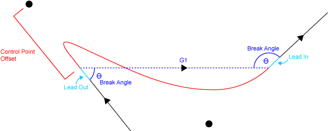
Table: Shape Skywriting (Single Bezier) Properties
| Property | Description |
|---|---|
|
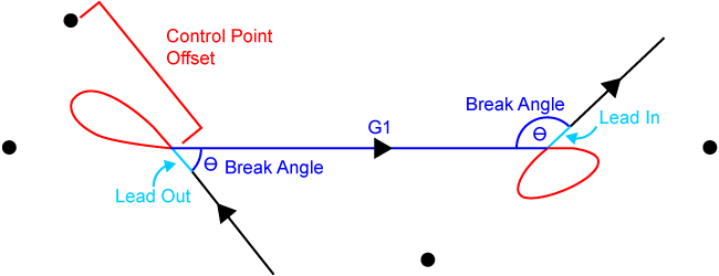
Control point offset |
Specify the distance between the inner control points and the points where the inserted Bezier curve connects to the lead in and lead out moves of the shapes. If you increase this value, the size of the Bezier curve also increases. |
|
Break angle |
Specify, in degrees, the maximum angle where your process requires a skywriting transition. Refer to the Using the Break Angle to Limit Shape Skywriting (Single Bezier) section that follows. |
Using the Break Angle to Limit Shape Skywriting (Single Bezier)
You can use the Break angle property to limit where CADFusion inserts a Bezier curve between consecutive, non-tangent shapes. CADFusion inserts a Bezier curve between consecutive, non-tangent shapes when the angle they form is less than or equal to the value you specify for the Break angle property:
- If you set the Break angle property to a value of 180°, CADFusion always inserts Bezier curves.
- If you set the Break angle property to a value of 0°, CADFusion does not insert Bezier curves. This functionality is the same as using LINEAR (G1) for your Shape transition type.
When you enable Shape Skywriting (Single Bezier) mode, CADFusion uses the process that follows:
- CADFusion generates a LINEAR (G1) transition move between the lead out move of the first shape and the lead in move of the second shape.
- The lead move of each shape makes a break angle with the LINEAR (G1) transition move. CADFusion calculates these angles as follows:
- If one or both of the angles are less than or equal to the value you specified for the Break angle property, CADFusion inserts one Bezier curve as the transition move between the shapes in the generated AeroScript or AeroBasic program. It does not use the LINEAR (G1) transition move that it generated in Step 1.
- If the two angles are greater than the value you specified for the Break angle property, CADFusion uses the LINEAR (G1) transition move that it generated in Step 1. It puts the transition move between the shapes in the generated AeroScript or AeroBasic program. It does not use a Bezier curve.