DC Brush/Voice Coil Motor Connections
The configuration shown in DC Brush/Voice Coil Maximum Voltage Motor Configuration is an example of a typical DC brush or Voice Coil motor connection. Refer to DC Brush/Voice Coil Motor Phasing for information on motor phasing.
When you connect the motor between amplifier phases A and C, it will produce twice the nominal bus voltage across the motor. This is because phase C will generate the same voltage as phase A but with opposite polarity. To generate the nominal bus voltage, connect the motor between Phase A and RT. RT is the 0 V return path for the motor power supply.
Use the lowest voltage configuration possible to minimize heat generation in the amplifier.
Figure 2-8: DC Brush/Voice Coil Maximum Voltage Motor Configuration
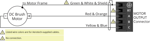
Figure 2-9: DC Brush/Voice Coil Minimum Heating Motor Configuration (Recommended)
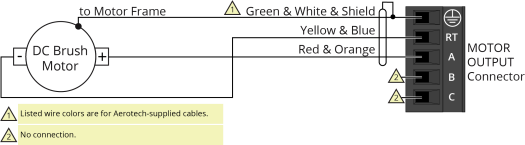
Table 2-9: DC Brush/Voice Coil Voltage Output Configuration
|
Connection |
XL5e 20-VB4 |
XL5e10-VB4 |
XL5e10-VB5 |
XL5e10-VB6 |
|---|---|---|---|---|
|
A to C |
80 V |
80 V |
120 V |
160 V |
|
A to RT |
40 V |
40 V |
60 V |
80 V |
Table 2-10: Wire Colors for Aerotech-Supplied DC Brush/Voice Coil Motor Cables
|
Pin |
Wire Color Set 1(1) |
Wire Color Set 2 |
Wire Color Set 3 |
|---|---|---|---|

|
Green & White & Shield (2) |
Green/Yellow & Shield |
Green/Yellow & Shield |
|
A |
Red & Orange |
Red |
Red & Orange |
|
C |
Yellow & Blue |
Black |
Yellow & Blue |
|
(1) Wire Color Set #1 is the typical wire set used by Aerotech. (2) “&” (Red & Orange) indicates two wires; “ / ” (Green/White) indicates a single wire. |
|||