Calibration Topic
Use the Calibration topic to configure calibration files (1D, 2D, and Galvo 2D) and Galvo Power Correction files. You can also create and merge Galvo 2D Axis calibration files. This topic and its
Calibration Module
Use the Calibration module to configure axis calibration files (1D, 2D, and Galvo 2D) and Galvo Power Correction files. You can see the status of each file and modify the configured calibration files on the controller.
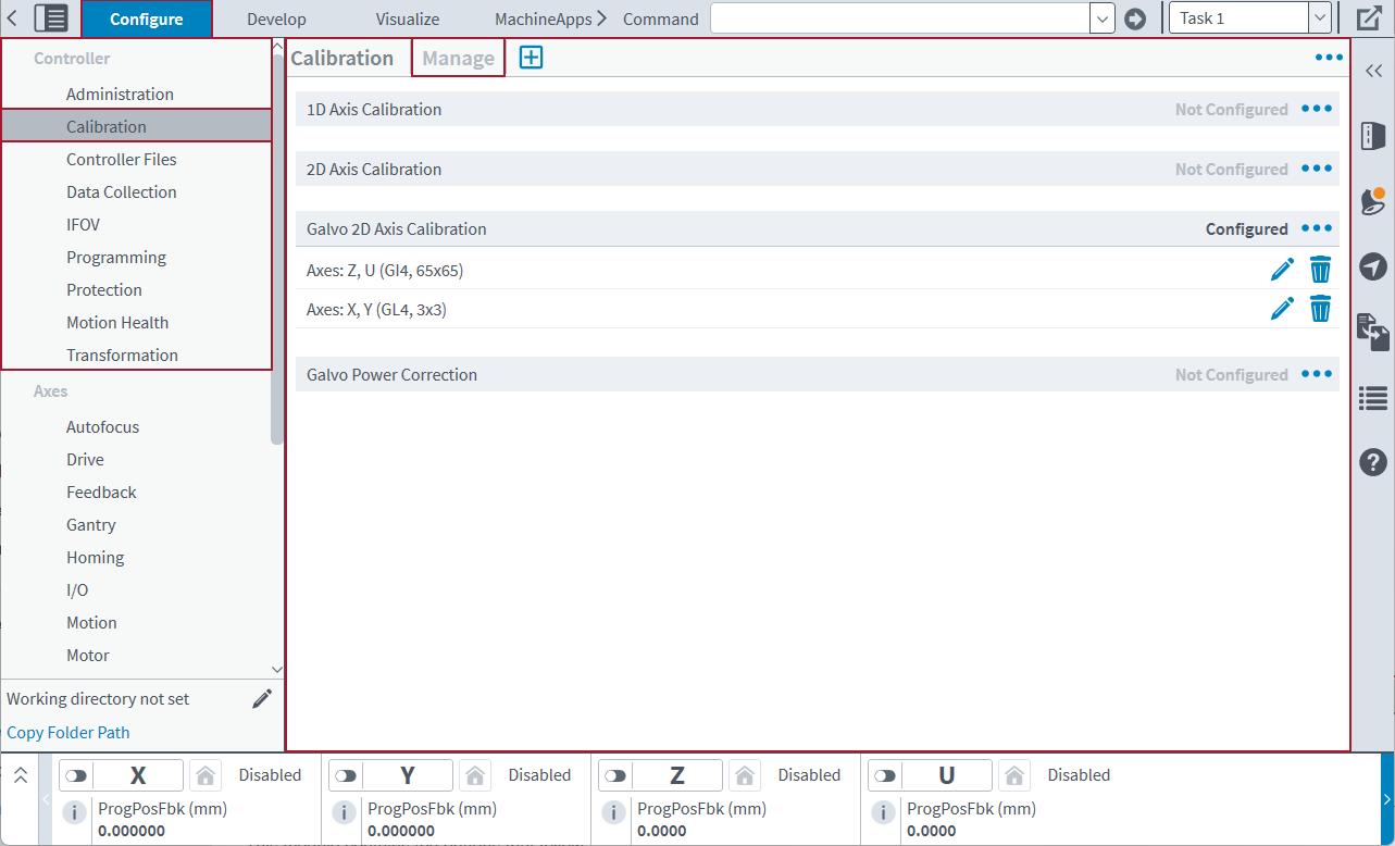
This module contains the buttons that follow:
- Module Menu: Shows more things you can do, such as download, upload, or remove a file.
- Add Empty Table: Add an empty Galvo 2D Axis Calibration table.
- Add Table From File: Add a Galvo 2D Axis Calibration table from a .cal or .csv file.
- In the Configure workspace, find the Controller category. Then select the Calibration topic.
- Select the Menu
 button next to the calibration file type that you want to download. Then click Download.
- In the Configure workspace, find the Controller category. Then select the Calibration topic.
- Select the Menu button next to the calibration file type that you want to upload. Then click Upload.
- In the Configure workspace, find the Controller category. Then select the Calibration topic.
- Select the Menu button next to the calibration file type that you want to remove. Then click Remove.
For more information about 1D, 2D, and Galvo 2D axis calibration and the correct formats for calibration tables and files, see Axis Calibration. For more information about Galvo Power Correction files, see Galvo Power Correction.
As an alternative to the Configure workspace, you can use the CalibrationLoad() function to load and activate axis calibration and Galvo Power Correction files without resetting the controller. For more information, see Calibration Functions.
Working With Galvo 2D Axis Calibration Tables
IMPORTANT: Galvo, GI4, and GL4 functionality are available only if you are using a PC-based controller.
Use the Calibration module to create, open, edit, and merge Galvo 2D Axis calibration files that you can use with an Aerotech controller. Before you can make a new calibration table, you must first configure the galvo scanner axes. Do the Machine Setup process to configure these axes. See Machine Setup for more information. Each calibration table is then applied to its related galvo scanner axes.
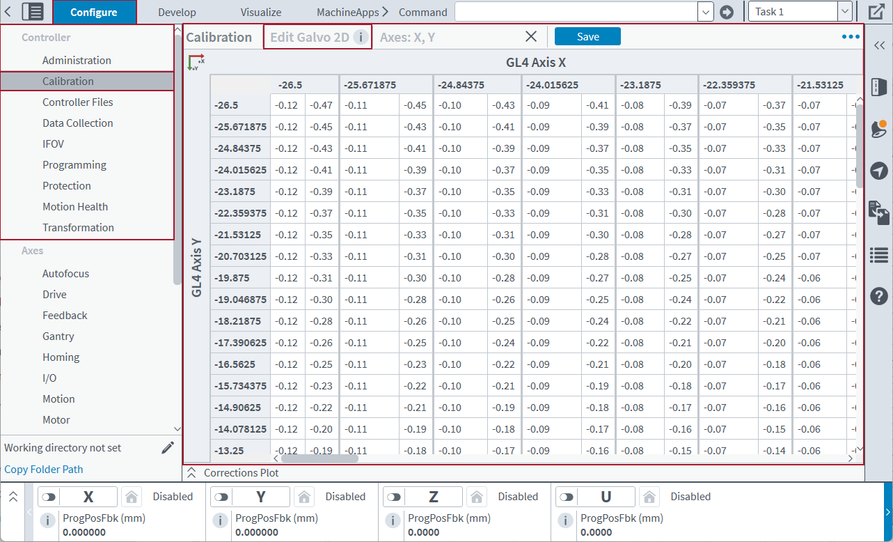
The Add Galvo 2D and Edit Galvo 2D screens of this module contains the buttons that follow.
Table: Galvo 2D Toolbar
| Name | Type | Description |
|---|---|---|
|
Configured Tables |
Button |
Shows the correction tables for the axes in the configured Galvo 2D Axis calibration file that you are currently adding or editing. |
|
Save File |
Button |
Saves the changes that you make to an existing calibration table in the configured Galvo 2D Axis Calibration. The calibration table must be open in the Calibration module. |
| Merge |
Button |
Merges axis calibration from the configured Galvo 2D Axis Calibration file into the selected file. This button is available only if the configured Galvo 2D Axis Calibration file contains a calibration table for the same axes as those corrected by the calibration file that you are currently adding. |
|
Menu |
Buttons |
The buttons that follow are part of the Menu. To find them, click the Menu (
|
|
Corrections Plot |
Button |
Expands or collapses the Corrections Plot drawer. For more information, see Corrections Plot. |
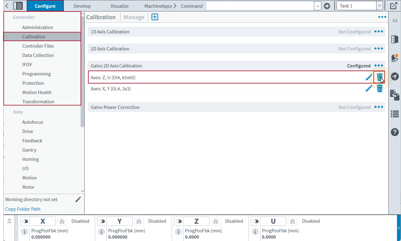
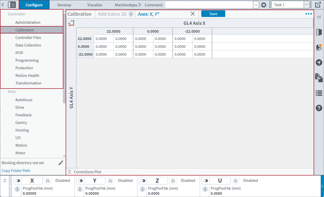
If a Galvo 2D Axis Calibration file is configured, you can look at the calibration tables. (See Figure: Calibration Module - Manage Screen.) To remove a calibration table, use the Remove button.
Add Galvo 2D Axis Calibration
You can add a calibration table to the configured Galvo 2D Axis Calibration. It is not necessary to upload a calibration file before you add a new table.
- In the Configure workspace, find the Controller category. Then select the Calibration topic. Make sure that the Manage screen is in view.
- Click the Add button. Then select Empty Table. A Create New Galvo 2D Axis Calibration File dialog comes into view.
- Enter the correction values.
- Click Save. Then click Yes to continue.
- If you add a GL4 calibration table and the Sample Distance for either axis is greater than 1 mm, a dialog comes into view and asks if you want to maximize the table dimensions. Do one of the options that follow:
- Click Yes to automatically interpolate the table to use the maximum possible Sample Counts. Aerotech recommends that you do this to decrease table discontinuities.
- Click No to make the table keep its current Sample Counts.
- Click Yes to reset the controller.
- To close the calibration table and go back to the Manage screen, click the X on its tab in the toolbar.
IMPORTANT: If the axes are already corrected by the configured Galvo 2D Axis Calibration, click Merge to merge the corrections you entered with the corrections that are active on the controller.
IMPORTANT: If you click Yes and maximize the table, this will substantially increase the number of correction values.
Edit Galvo 2D Axis Calibration
You can also edit a calibration table in the configured Galvo 2D Axis Calibration.
- In the Configure workspace, find the Controller category. Then select the Calibration topic. Make sure that the Manage screen is in view.
- Find the configured Galvo 2D Axis Calibration that you want to change. Click the Edit button. The Edit Galvo 2D screen comes into view.
- Make your edits. Click Save. Then click Yes to continue.
- Click Yes to reset the controller.
- To close the calibration table and go back to the Manage screen, click the X on its tab in the toolbar.
For more information about Galvo 2D Axis Calibration files, see the Galvo 2D Axis Calibration section on the Axis Calibration page.
Scanner Orientation
When you make an empty Galvo 2D Axis Calibration table, the Create New Galvo 2D Axis Calibration File dialog shows a Scanner Orientation feature. The orientation you select will determine how the application shows the table in the Calibration module, based on the positive direction of each axis. The scanner orientation does not have an effect on the contents of the table. It only changes the view of the table. Make sure you select the scanner orientation that corresponds to the physical configuration of your galvo scanner.
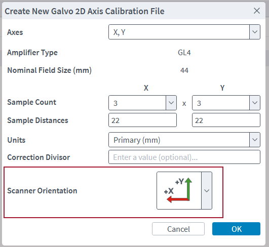
For example, if you select the Scanner Orientation shown in the figure that follows, the application shows the table with X positive leftwards and Y positive upwards.
After you make a table, you can also use Edit File Properties to change the Scanner Orientation.
Corrections Plot
When you add or edit a Galvo 2D Axis Calibration table, the Corrections Plot drawer shows a visualization of the correction vectors. To expand or collapse the Corrections Plot drawer, click the up or down arrows on the left.
The colors of the plot identify the relative magnitudes of the corrections. The corrections with the smallest magnitudes show in blue, and the corrections with the largest magnitudes show in red. The remaining corrections show in green.
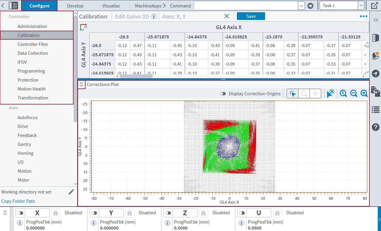
Table: Corrections Plot Viewing Options
| Name | Type | Description |
|---|---|---|
|
Display Correct Origins |
Button |
Shows or hides the correction origins on the plot. |
|
Select Vectors |
Button |
Use the left and right mouse buttons to select vectors on the plot that you are looking at. When you select a vector on the plot, the application automatically selects its correction in the table. When you select a correction in the table, the application automatically selects its vector on the plot. Click the Clear Selection button to remove all the vector selections from the plot. |
|
Zoom |
Button |
Zooms in on a range of vectors when you use the left mouse button to click and drag on the plot. |
|
Pan |
Button |
Changes the range of vectors that you are looking at when you use the left mouse button to click and drag on the plot. |
|
Clear Selection |
Button |
Removes the vector selection from the plot. |
|
Reset Zoom |
Button |
Resets the zoom level on the plot. |
|
Zoom Out |
Button |
Decreases the zoom level on the plot. |
|
Zoom In |
Button |
Increases the zoom level on the plot. |
GL4 Scanner Calibration Files
Use the Calibration module to create and save calibration files in either the .cal or .csv file format. A GL4 calibration file in the .cal format can have a maximum of 138,000 points. The number of samples per axis must be odd and range from 3 to 32,769. The positions and corrections are stored in counts, primary units, or secondary units. The field of view can be any size.
IMPORTANT: For accurate results, make sure the center position of a calibration file is always (0,0). If the center position is not aligned, you must correct it through manual alignment by manually moving the scanner position relative to the working surface. For information about how to do this, refer to your AGV product hardware manual. To download your manual from www.aerotech.com, go to the Mechanical section of Manuals & Help Files.
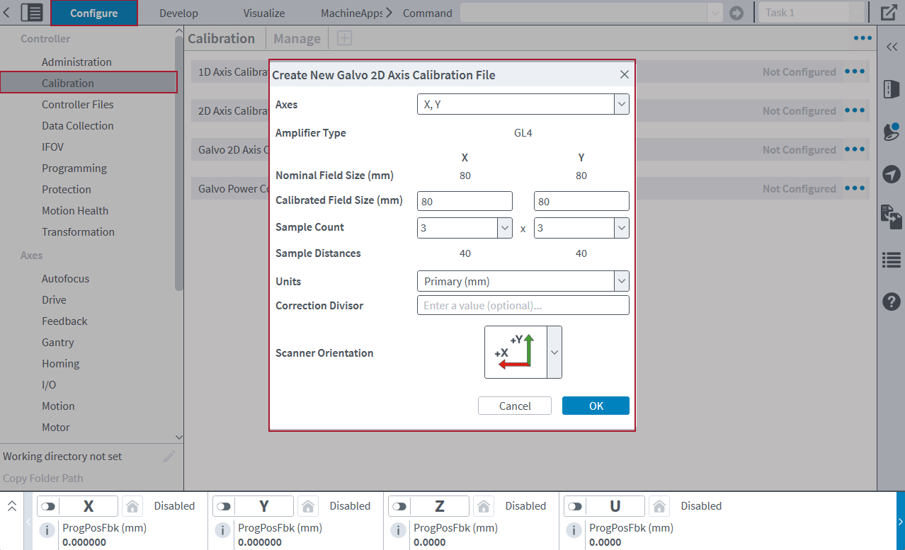
Create a File
- In the Configure workspace, find the Controller category. Then select the Calibration topic. Make sure that the Manage screen is in view.
- On the toolbar, click the Add button. Then select Empty Table. The Create New Galvo 2D Axis Calibration File dialog comes into view.
- Select the axes of the GL4 scanner for which you want to make a calibration file. The Amplifier Type and Nominal Field Size (mm) come into view.
- Enter the Calibrated Field Size for each axis of the calibration table. These values determine the dimensions of the field that the calibration file will correct. The Calibrated Field Size values must be greater than zero and less than or equal to the Nominal Field Size.
- Select or type the number of samples per axis of the calibration table. The number of samples per axis, together with the Calibrated File Size, determine the sample distances. Each Sample Count must be an odd integer between 3 and 45,999. The total number of correction values cannot be more than 138,000 points.
- The Sample Distances for each axis of the calibration table come into view. These values are the distances between each correction position for the axes. These values are specified in units. These distances are automatically calculated.
- Select the Units you want to use for the sample distances and corrections.
- (Optional) Enter a value in the Correction Divisor value box. The correction divisor changes correction values from units to units / divisor.
- Select the Scanner Orientation you want to use for the table.
- Click OK to close the dialog.
Use a CSV File Format for the GL4 Calibration File
If you use a .csv file as a GL4 calibration file, the .csv file must obey these guidelines:
- The number of rows and columns must be odd.
- The total number of correction values cannot be more than 138,000 correction points.
- Each row must have the same number of entries.
- Each correction vector must be in the format that follows:
"Channel 1 Correction Value, Channel 2 Correction Value, Channel 3 Correction Value" - Each subsequent entry must be separated by commas, and the entire entry must be inside double quotation marks (""). This is an example of a row from a three-column .csv file:
"-3,1,0","-2,0,0","-3,-1,0" - The third channel in the .csv file is necessary, but when you import a .csv file as a .cal file, this channel is ignored.
- The columns and rows must be evenly distributed over the field of view.
GI4 Scanner Calibration Files
Use the Calibration module to create and save calibration files in the .cal or .csv file format. A GI4 calibration file in the .cal file format is always 65 x 65 entries. If you save a file that has other dimensions, then the table automatically scales to 65 x 65 entries. The field of view is stored in counts. For a 16-bit scanner resolution, the file shows a range of -32768 to 32767. For a 20-bit scanner resolution, the file shows a range of -524288 to 524287.
IMPORTANT: For accurate results, make sure the center position of a calibration file is always (0,0). If the center position is not aligned, you must correct it through manual alignment by manually moving the scanner position relative to the working surface. For information about how to do this, refer to your AGV product hardware manual. To download your manual from www.aerotech.com, go to the Mechanical section of Manuals & Help Files.
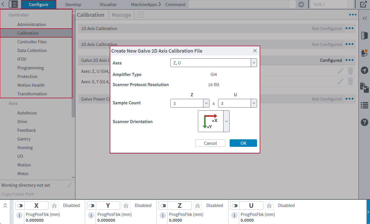
Create a File
- In the Configure workspace, find the Controller category. Then select the Calibration topic. Make sure that the Manage screen is in view.
- On the toolbar, click the Add button. Then select Empty Table. The Create New Galvo 2D Axis Calibration File dialog comes into view.
- Select the axes of the GI4 scanner for which you want to make a calibration file. The Amplifier Type and Scanner Protocol Resolution come into view.
- Select or type the number of samples per axis of the calibration table. Each Sample Count must be between 2 and 65.
- Select the Scanner Orientation that you want to use for the table.
- Click OK to close the dialog.
Use a CSV File Format for the GI4 Calibration File
If you want to use a .csv file as a GI4 calibration file, the .csv file must obey these guidelines:
- Each row must have the same number of entries.
- Each correction vector must be in the format that follows:
"Channel 1 Correction Value, Channel 2 Correction Value, Channel 3 Correction Value" - Each subsequent entry must be separated by commas, and all of the entries must be inside double quotation marks (""). This is an example of a row from a three-column .csv file:
"-3,1,0","-2,0,0","-3,-1,0" - The third channel in the .csv file is necessary, but when you import a .csv file as a .cal file, this channel is ignored.
- The columns and rows must be evenly distributed over the field of view.
- The field of view is determined by the scanner protocol resolution:
- In a file with 16-bit scanner protocol resolution, the first entry corresponds to the point (-32768, -32768). The last entry corresponds to the point (32767, 32767). Each intermediate entry evenly divides this range.
- In a file with 20-bit scanner protocol resolution, the first entry corresponds to the point (-524288, -524288). The last entry corresponds to the point (524287, 524287). Each intermediate entry evenly divides this range.
- In the .csv file, as you read the rows from top to bottom, the entries correspond to an increase in the Axis 2 position. As you read the columns from left to right, the entries correspond to an increase in the Axis 1 position.
Interpolation
Interpolation lets you make coarse mark and measure calibrations and increase their density.
- Collect a coarse set of measurements across the full field of view (FOV) of the scanner lens.
- Save the new calibration.
- Use Edit File Properties to adjust the sample count values for each axis.
- Select OK. The application will automatically rescale the table to your new sample count. Then it uses bi-cubic interpolation to fill in all the positions between your initial coarse measurements. This creates accurate corrections for the entire lens FOV.
Aerotech recommends that you interpolate calibration tables to the maximum permitted size to decrease discontinuities in the calibration performance.
Change Precision in Calibration Files
To adjust the number of decimal places of precision in your calibration files, use the Precision settings. To do this, select the Menu () button and click Settings. In the Settings dialog, make sure the Calibration tab is selected.
Display Precision
Display Precision is the number of decimal places that the application shows for a correction value. You can specify a value from 0 to 15. If you decrease the display precision, the application shows the values rounded to fewer decimal places. Display precision only changes how the application shows the value. It does not have an effect on the precision of the values in your calibration file.
Output Precision
Output Precision is the number of decimal places that the application applies to a correction value when you save the calibration file.
To get access to edit the Output Precision box, you must enable the Use output precision when saving files toggle. When you save the calibration file, correction values that have more decimal places than the specified output precision value are rounded. Correction values with fewer decimal places than the specified value are zero-padded.
If the Use output precision when saving files toggle is off, when you save the calibration file, the correction values are written to the file with as many or as few decimal places as are necessary for the full correction value.
IMPORTANT: If you use fixed precision when you save a calibration file, the correction values can lose precision. You will overwrite the original full-precision correction values with the rounded correction values.
Merge Calibration Files
You can merge two calibration files to get one calibration file with the corrections from both files. Typically, you merge files to improve calibration by merging measured corrections with the corrections that are active on the controller.
- Open the calibration file that you want to merge:
- Click the Add button on the toolbar. Then select Table From File. The Open dialog comes into view.
- Select the file you want and click the Open button. The Add Galvo 2D screen comes into view.
- Click the Merge button on the toolbar. This button is available only if the configured Galvo 2D Axis Calibration file contains a calibration table for the same axes as those corrected by the calibration file that is currently open. The application adds the corrections from the configured calibration table to the corrections of the file that is currently open.
- Click the Save button on the toolbar to update the calibration that is active on the controller.
You can also use the Merge File... menu item to merge a calibration file with a .cal or .csv file in the MDK File System.
- Open one of the calibration files that you want to merge:
- Click the Add button on the toolbar. Then select Table From File. The Open dialog comes into view.
- Select the file you want and click the Open button.
- Click the Menu () button. Then select Merge File.... The Open dialog comes into view.
- Select the file you want to merge into the current file and click the Open button.
The corrections from the file that you selected are added to the corrections of the file that is currently open.
Rules for Merging Files
When you merge files, you must obey the rules that follow:
- You cannot merge a file with itself.
- Corrections in the open file that are out of the field of view of the file you selected to merge do not change.
- Corrections in the open file that do not align with corrections in the file you selected to merge are interpolated.
- These rules apply to existing GL4 calibration files:
- The file being merged cannot have a samples per axis dimension larger than 45,999.
- The units of both files must be the same.
- These rules apply to existing GI4 calibration files:
- The file being merged must have dimensions of 65 x 65 entries.
- The file being merged must have corrections in counts.
- The file being merged must use the same scanner protocol resolution.


