Cutter Radius Compensation
IMPORTANT: This feature applies to dominant axes only. To configure an axis as dominant, use the AxisType Parameter.
Cutter radius compensation compensates for the size of a cutting tool by causing the controller to maintain a constant offset that is perpendicular to the programmed path in a two-dimensional plane. You can use this feature to compensate for the radius of a cutting tool or the width of a laser. When you enable cutter radius compensation, the controller gradually applies the offsets during a lead-on move. When you disable, it gradually removes the offsets during a lead-off move.
Before you use cutter radius compensation, make sure you that know the important information that follows:
- When you use the
Home()function on an axis, the controller immediately disables cutter radius compensation. It does not gradually remove the offsets during a lead-off move. - When cutter radius compensation is enabled, it causes the controller to activate lookahead. For more information, see Lookahead Synchronization.
- When cutter radius compensation is enabled, the controller maintains an offset from the programmed path during coordinated motion (
MoveLinear(),MoveCw(), andMoveCcw()motion) by keeping the center of the cutting tool on a line that is perpendicular to the programmed path. DuringMoveRapid()motion, the controller does not try to maintain the offset becauseMoveRapid()does not follow a coordinated path.
For information about G-code commands, see G-Code Programming.
Specify the Axes
Use the CutterCompensationSetAxes() function or the G44 command to specify the axes that are used for cutter radius compensation.
- You must specify the axes in the same order they are specified in the circular plane.
- Make sure the axes are the same axes specified in the
G17,G18, orG19command. See Coordinated Arc Motion G-Code Programming . - If you use cutter radius compensation at the same time as corner rounding or cutter offset compensation, then you must use the same axes for those features.
Program Example: Specify Axes
// Specify axis X as the X-plane axis.
// Specify axis Y as the Y-plane axis.

CutterCompensationSetAxes([X, Y])
// or
G44 X Y
Sets the axes to use in cutter offset and cutter radius compensation.
Arguments
$cutterAxes The axes to use. You must specify either 2 or 3 axes.
Specify the Size of the Cutting Tool
Use the CutterCompensationSetRadius() function to specify the radius of the cutting tool or the width of the laser. Alternatively, you can use the G43 command to override the radius used for cutter radius compensation. The radius to compensate for is the value specified by the CutterCompensationSetRadius() function or G43 command. Use these commands only when cutter radius compensation is disabled.
Program Example: Specify Radius
// Specify the radius of the cutting tool or width of the laser to be 0.01 units.

CutterCompensationSetRadius(0.01)
// or
G43 P0.01
Sets the radius to use in cutter radius compensation.
Arguments
$cutterRadius The cutter radius.
Enable Cutter Radius Compensation
You can use the G41 or G42 command to enable cutter radius compensation mode. The controller gradually applies the offsets during a lead-on move. We recommend that you put the coordinated move you want to use for the lead-on move on the same program line as the G41 or G42 command. If you do not, the controller uses the next coordinated move that it executes as the lead-on move. If the controller cannot find the next coordinated move, it does not use cutter radius compensation.
Tip: Put the lead-on move on the same program line as the G41 or G42 command to make sure cutter radius compensation offsets are applied.
WARNING: Before you apply a lead-on or lead-off move, make sure the moves will not damage the tool or part.
Cutter Path Left
The G41 command enables cutter radius compensation so that the cutter path is to the left of the programmed path, relative to the direction of motion.
Program Example: Generate Lead-On Move Left
// Enable cutter radius compensation to the left of the programmed path and generate a lead-on move.
G41 G1 X10 Y10
Figure: G41 Lead-On Move Left shows the lead-on move from Point A to Point B where cutter radius compensation is configured with the cutter path to the left of the programmed path. In this figure, cutter radius compensation was configured with the G41 command.
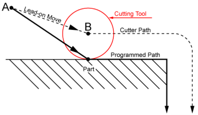
The CutterRadiusActiveLeft bit of Task Status 2 shows the active state of the G41 command. To see the active state of the G-code command, refer to this bit in the Tasks → Task Status 2 tab of the Automation1 Status Utility. You can also retrieve the status of this bit by using the StatusGetTaskItem() function. For information about how to use this function, refer to the StatusGetTaskItem() example that includes the $additionalData argument in Controller Status Functions.
Cutter Path Right
The G42 command enables cutter radius compensation so that the cutter path is to the right of the programmed path, relative to the direction of motion.
Program Example: Generate Lead-On Move Right
// Enable cutter radius compensation to the right of the programmed path.
G42

// The controller generates a lead-on move while it generates the move that follows.
G1 X5 Y-10
Figure: G42 Lead-On Move Right shows the lead-on move from Point A to Point B where cutter radius compensation is configured with the cutter path to the right of the programmed path. In this figure, cutter radius compensation was configured with the G42 command.
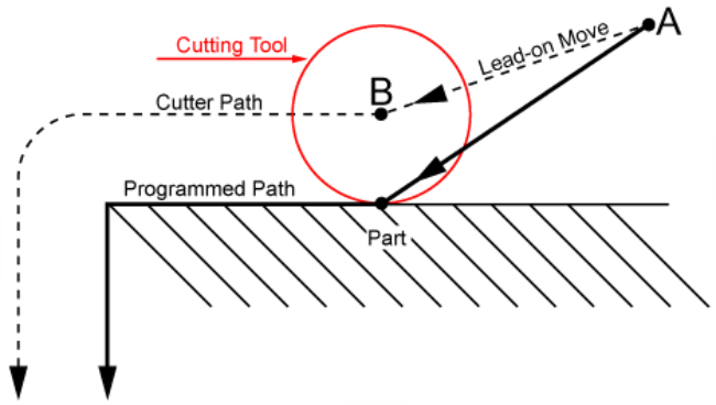
The CutterRadiusActiveRight bit of Task Status 2 shows the active state of the G42 command. To see the active state of the G-code command, refer to this bit in the Tasks → Task Status 2 tab of the Automation1 Status Utility. You can also retrieve the status of this bit by using the StatusGetTaskItem() function. For information about how to use this function, refer to the StatusGetTaskItem() example that includes the $additionalData argument in Controller Status Functions.
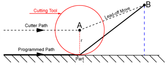
Disable Cutter Radius Compensation
Use the G40 command to disable cutter radius compensation. The controller gradually removes the offsets during a lead-off move. We recommend that you put the coordinated move you want to use for the lead-off move on the same program line as the G40 command. If you do not, the controller uses the next coordinated move that it executes as the lead-off move. If the controller cannot find the next coordinated move, it does not remove compensation for the radius of the cutting tool.
Tip: Put the lead-off move on the same line as the G40 command to make sure that all compensation is removed.
WARNING: Before you apply a lead-on or lead-off move, make sure the moves will not damage the tool or part.
Program Example: Disable Cutter Radius Compensation
// Disable cutter radius compensation and generate a lead-off move.
G40 G1 X10 Y10
Figure: G40 Lead-Off Move shows the lead-off move from Point A to Point B where cutter radius compensation is configured to remove the cutter offsets that were enabled by the G41 or G42 command from the cutter path to produce the original, programmed path. In this figure, cutter radius compensation was configured with the G41 command (lead-on move left) and the G40 command (lead-off move).