Cutter Offset Compensation
IMPORTANT: This feature applies to dominant axes only. To configure an axis as dominant, use the AxisType Parameter.
Cutter offset compensation compensates for the offsets of a cutting tool with regard to the programmed path. This is done by translating the entire programmed path in either the two-dimensional or three-dimensional plane, so you do not have to change the programmed path to adjust for tool offsets. When you enable cutter offset compensation, the controller gradually applies the offsets during a lead-on move. When you disable, it gradually removes the offsets during a lead-off move.
When you use the Home() function on an axis, the controller immediately disables cutter offset compensation. It does not gradually remove the offsets during a lead-off move.
For information about G-code commands, see G-Code Programming.
Specify the Axes
Use the CutterCompensationSetAxes() function or the G44 command to specify the axes that make up the X-Y or X-Y-Z plane that is used for cutter offset compensation.
- If you want to compensate for tool length, you must specify the third axis (Z plane).
-
Cutter offset compensation will occur on all axes specified by the
CutterCompensationSetAxes()function or theG44command even if that axis is not explicitly included in the lead-on move. If you do not specify the third axis, cutter offset compensation will be configured for two axes. - If you use cutter offset compensation at the same time as corner rounding or cutter radius compensation, then you must use the same axes for those features. For more information, see Corner Rounding Functions or Cutter Radius Compensation.
Program Example: Specify Axes
// Specify axis X as the X-plane axis.
// Specify axis Y as the Y-plane axis.
// Specify axis Z as the Z-plane axis.

CutterCompensationSetAxes([X, Y, Z])
// or
G44 X Y Z
Sets the axes to use in cutter offset and cutter radius compensation.
Arguments
$cutterAxes The axes to use. You must specify either 2 or 3 axes.
Specify the Tool Offsets
Use the CutterCompensationSetOffsets() function to specify the tool offsets and lengths. You can specify zero, or any positive or negative value for the tool offsets and lengths. Use this command only when cutter offset compensation is disabled.
Program Example: Specify Tool Offsets
// Specify the x-offset as 1, the y-offset as -2, and the length of the cutting tool as 3.
CutterCompensationSetOffsets([1, -2, 3])
Sets the offsets to use in cutter offset compensation. The number of offsets that you specify must be the same as the number of axes specified to CutterCompensationSetAxes().
Arguments
$cutterOffsets The cutter offsets. You must specify either 2 or 3 offsets.
Enable Cutter Offset Compensation
You can use the G143 or G144 command to enable cutter offset compensation mode. The controller gradually applies the offsets during a lead-on move. We recommend that you put the coordinated move you want to use for the lead-on move on the same program line as the G143 or G144 command. If you do not, the controller uses the next coordinated move that it executes as the lead-on move. If the controller cannot find the next coordinated move, it does not use cutter offset compensation.
Tip: Put the lead-on move on the same program line as the G143 or G144 command to make sure cutter offset compensation offsets are applied.
WARNING: Before you apply a lead-on or lead-off move, make sure the moves will not damage the tool or part.
Add Offsets
The G143 command enables cutter offset compensation so that the cutter path adds the tool offsets and lengths to the programmed path.
Program Example: Add Tool Offsets
// Add tool offsets to the programmed path during a lead-on move.
G143 G1 X10 Y10
Figure: G143 Lead-On Move Positive shows the lead-on move from Point A to Point B where cutter offset compensation is configured to add all offsets to the programmed path to produce the cutter path. In this figure, cutter offset compensation was configured with the G143 command.
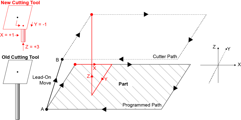
The CutterOffsetActivePositive bit of Task Status 2 shows the active state of the G143 command. To see the active state of the G-code command, refer to this bit in the Tasks → Task Status 2 tab of the Automation1 Status Utility. You can also retrieve the status of this bit by using the StatusGetTaskItem() function. For information about how to use this function, refer to the StatusGetTaskItem() example that includes the $additionalData argument in Controller Status Functions.
Subtract Offsets
The G144 command enables cutter offset compensation so that the cutter path subtracts the tool offsets and lengths from the programmed path.
Program Example: Cutter Path Subtracts Tool Offsets
// Enable negative tool offsets.
G144

// Subtract tool offsets from the programmed path during the lead-on move.
G1 X10 Y10
Figure: G144 Lead-On Move Negative shows the lead-on move from Point A to Point B where cutter offset compensation is configured to subtract all offsets from the programmed path to produce the cutter path. In this figure, cutter offset compensation was configured with the G144 command.
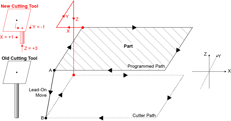
The CutterOffsetActiveNegative bit of Task Status 2 shows the active state of the G144 command. To see the active state of the G-code command, refer to this bit in the Tasks → Task Status 2 tab of the Automation1 Status Utility. You can also retrieve the status of this bit by using the StatusGetTaskItem() function. For information about how to use this function, refer to the StatusGetTaskItem() example that includes the $additionalData argument in Controller Status Functions.
Disable Cutter Offset Compensation
Use the G149 command to disable cutter offset compensation so that the cutter path removes the tool offsets and lengths from the programmed path. The controller gradually removes the offsets during a lead-off move. We recommend that you put the coordinated move you want to use for the lead-off move on the same program line as the G149 command. If you do not, the controller uses the next coordinated move that it executes as the lead-off move. If the controller cannot find the next coordinated move, it does not remove compensation for the offsets and length of the cutting tool.
Tip: Put the lead-off move on the same line as the G149 command to make sure that all compensation is removed.
WARNING: Before you apply a lead-on or lead-off move, make sure the moves will not damage the tool or part.
Program Example: Disable Tool Offsets
// Disable tool offsets to the programmed path during the lead-off move.
G149 G1 X10 Y10
Figure: Lead-Off Move shows the lead-off move from Point A to Point B where cutter offset compensation is configured to remove the cutter offsets that were enabled by the G143 or G144 command from the cutter path to produce the original, programmed path. In this figure, cutter offset compensation was configured with the G144 command (lead-on move negative) and the G149 command (lead-off move).


