PSO tools configure PSO on Aerotech motion control systems. For more information on PSO, refer to Automation1 or A3200 Help.
The Drive Type of a PSO tool determines whether it is available to use in CADFusion projects that target Automation1 or A3200 motion control systems. For example, you can use a PSO tool with a Drive Type of XC4 in either CADFusion projects that target the Automation1 motion control system or CADFusion projects that target the A3200 motion control system. However, you can only use a PSO tool with a Drive Type of NDriveCP in projects that target the A3200. For more information about supported drive types, refer to Automation1 or A3200 Help.
A tool has four phases. The table that follows shows the code that is generated for each phase of a PSO tool and the specified time in a program when the code executes.
Table: Tool Phases and Code Execution
| Tool Phase | PSO Code | Description |
|---|---|---|
|
Initialization |
PSO Initialization Code |
PSO tools generate code to initialize the PSO hardware. The code executes one time, before each time that you use the tool. If you only use one tool, this code executes one time at the start of the AeroScript or AeroBasic program. If you want to use more than one tool, refer to Using More Than One Tool. |
|
On |
PSO code to enable distance tracking, waveform generation, or set the state of the PSO output |
Before a shape starts, the PSO hardware is enabled based on the type of PSO that you configure. The PSO distance tracking hardware and the waveform generation hardware are enabled, if applicable. Or, the PSO output is configured to be active. By default, if the shape has a lead in move, the PSO hardware is enabled before the lead in move. You can change when the code executes in the Code Placement Settings for the tool. |
|
Off |
PSO code to disable distance tracking, waveform generation, or reset the state of the PSO output |
After a shape completes, the PSO hardware is disabled. By default, if a shape has a lead out move, the PSO hardware is disabled after the lead out move. You can change when the code executes in the Code Placement Settings for the tool. |
|
Teardown |
Not available |
PSO tools do not have teardown code. |
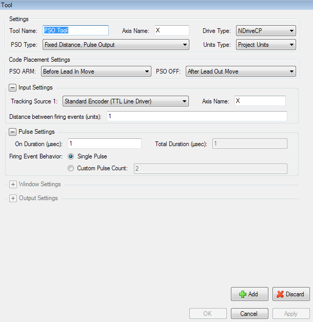
Use the Tool Catalog tab of the Catalog Manager to add or edit tools. For more information, refer to Add Tools or Edit Tools.
| Tool Setting |
Description |
|---|---|
|
The name of the tool. Each tool in your project must have a unique name. |
|
|
The name of the axis on which PSO is commanded. |
|
|
The type of drive on which PSO is commanded. |
|
|
The units of the distance values that you configure. You can use the same units as your project or you can use encoder counts. Refer to the Units Type section of this topic. |
|
|
Refer to the PSO Type section of this topic. |
|
|
The tracking source(s) and fixed distance between firing events. |
|
|
Pulse Settings |
The settings for the PSO pulse generator. Refer to PSO Pulse Settings Examples. |
|
Window Settings |
The settings for the PSO window hardware. |
|
Output Settings |
The drive-specific settings you use to configure PSO output. |
|
Code Placement Settings |
Controls when PSO hardware is enabled and disabled in relation to the lead moves of a shape. |
The Units Type setting specifies which units are used for the distance values that you configure. You can select Project Units or Counts. The distance values include:
NOTE: The PSO hardware operates on encoder counts and cannot do non-integer scaling. For true vector firing, all axes that are tracked must have the same distance unit per encoder count if you use Project Units or if you use Counts.
Project Units is the default. The distances that you specify are in the same units as your project. For example, if the primary units of your system are millimeters and you select Primary as the distance unit type for your project in the Project Settings dialog, then all the distance values that you configure in the PSO tool dialog will be millimeters.
Because the AeroScript PSO functions and AeroBasic PSO commands operate at the hardware level, the distance values must be specified in counts. Thus, when you export your project to AeroScript or AeroBasic, the PSO tool output for the tools that use Project Units includes code that converts the values that you entered from units to counts. During the conversion the values are rounded to the nearest count, which can cause a small difference between the actual firing distance and the firing distance that you expect.
Assume that the primary unit of your system is millimeters and the value of the CountsPerUnit parameter for the axis you are tracking is 800. If you specify the distance between firing events as 78 microns (0.078 millimeters), the result is that the pulses fire every 77.5 microns.

62.4 counts rounded to the nearest count is 62 counts.

WARNING: When you use Project Units, make sure that you specify the correct Axis Name for each tracking source in the Input Settings area of the PSO tool dialog. If the axis name is not correct, unexpected PSO behavior can occur.
When you select Counts, the distances that you specify are in encoder counts. Because the value of some axis parameters can have an effect on your PSO configuration, Aerotech recommends that you use counts only if you are an advanced user.
The table that follows shows the available types of PSO that you can select when you configure a PSO tool.
Table: PSO Type Settings
| PSO Type | Description |
|---|---|
|
Fixed Distance, Pulse Output |
The PSO hardware generates a sequence of pulses at each fixed-distance firing event. |
|
Fixed Distance, Pulse Output with Window Mask |
The PSO hardware generates a sequence of pulses at each fixed-distance firing event, if the firing event occurs while the position of an axis is within the specified range. |
|
Fixed Distance, Pulse Output Synchronized with Window |
The PSO hardware generates a sequence of pulses at each fixed-distance firing event. The tracking counters are reset when the position of an axis enters and exits the specified range, and the output stays inactive while the position of an axis is outside the specified range. |
|
Fixed Distance, Toggle Output |
The PSO hardware generates output that toggles to the opposite state at each fixed-distance firing event. |
|
Asynchronous, Fixed Window Output |
The PSO hardware generates output that corresponds to whether the tracked axes are inside the specified range. |
|
Asynchronous, Pulse Output |
The PSO hardware generates a sequence of pulses that is not tied to the position of an axis. |
|
Asynchronous, Pulse Output with Window Triggering |
The PSO hardware generates a sequence of pulses when the position of an axis enters or exits the specified range. |
|
Asynchronous, Continuously Active |
The PSO hardware generates output that is active for the full period between the Tool On phase and the Tool Off phase. |
Some of the other settings that you can configure are different depending on the PSO Type and Drive Type that you select. The possible settings include Input Settings, Pulse Settings, Window Settings, and Output Settings.