Aux Encoder Connectors
The Auxiliary Encoder connector gives you a second encoder channel. This channel is typically used for dual loop applications.
Use the AuxiliaryFeedbackType parameter to configure the drive rack to accept an encoder signal type.
Square Wave encoder signals: Square Wave Encoder (Auxiliary)
Absolute encoder signals: Absolute Encoder (Auxiliary)
Sine Wave encoder signals (with the -CT4 option): Sine Wave Encoder (Auxiliary) [-CT4 Option]
High resolution or high-speed encoders can require increased bandwidth for correct operation. Use the High Speed Mode of the AuxiliaryEncoderMultiplierSetup parameter to enable the high bandwidth mode. Because this mode increases sensitivity to system noise, use it only if necessary.
You can configure the Auxiliary Encoder interface as an output that will transmit encoder signals for external use. Use the DriveEncoderOutputConfigureInput() function to configure the Sine ±, Cosine ±, and Marker± connector pins as RS-422 outputs. You can only echo incremental square wave primary encoder inputs or, with the -CT2 or -CT4 option, incremental sine wave inputs. You cannot use the absolute encoder interface when you echo incremental signals.
Table 2-38: Aux Encoder Connector Pinout
|
Pin # |
Description |
In/Out/Bi |
Connector |
|---|---|---|---|
|
1 |
Auxiliary Sine + |
Bidirectional |
|
| Absolute Encoder Data + | Bidirectional | ||
|
2 |
Ground |
N/A |
|
|
3 |
Auxiliary Cosine - |
Bidirectional |
|
| Absolute Encoder Clock - | Output | ||
|
4 |
+5 V Auxiliary Encoder Power (500 mA max) |
Output |
|
|
5 |
Auxiliary Marker + |
Bidirectional |
|
|
6 |
Auxiliary Sine - |
Bidirectional |
|
| Absolute Encoder Data - | Bidirectional | ||
|
7 |
Ground |
N/A |
|
|
8 |
Auxiliary Cosine + |
Bidirectional |
|
| Absolute Encoder Clock + | Output | ||
|
9 |
Auxiliary Marker - |
Bidirectional |
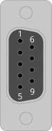
Table 2-39: Aux Encoder Mating Connector Ratings
| 9-Pin Solder Cup |
Backshell |
|
|---|---|---|
| Aerotech Part Number | ECK00137 | ECK01021 |
| Amphenol Part Number (1) | DE09P064TXLF |
17E-1724-2 |
| Maximum Wire Size | 20 AWG (0.5 mm2) |
N/A |
|
(1) Refer to the manufacturer website for additional information. |
||