Motor Power Output Connector
The drive can be used to control brushless motors (refer to Brushless Motor Connections).
For a complete list of electrical specifications, refer to Electrical Specifications
DANGER: Shock and Fire Hazard
Electrical wiring must be designed and installed in accordance with local electrical safety regulations to prevent the risk of fire and electrical shock.
The 4-pin terminal block style motor output connector is located on the front panel.
Table 2-5: Motor Power Output Connector Pinout
|
Pin |
Description |
Connector |
|---|---|---|
|
A |
Motor Phase A Output |
|
|
B |
Motor Phase B Output | |
| C | Motor Phase C Output | |
|
|
Motor Ground |
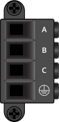

Table 2-6: Motor Power Output Mating Connector Ratings
| Specification | Description | |
|---|---|---|
| Type | 4-Pin Terminal Block | |
| Part Numbers | Aerotech: ECK02495 | |
| Phoenix: 1710352 | ||
|
Conductor Cross Section |
One conductor, stranded with ferrule and plastic sleeve | 8...14 AWG (2.5...10 mm2) |
| Two conductors (same cross-section), stranded, twin ferrule with plastic sleeve | 10...14 AWG (2.5...6 mm2) | |
| Tightening Torque | 1.7...1.8 N·m | |
| Conductor Insulation Strip Length | 12 mm (0.5 in) | |
|
(1) Refer to the manufacturer website for additional information. |
||