Bus Link Connector
The BUS LINK connector provides access to the internal DC motor bus supply (DC link) voltage and shunt (brake) resistor connections. The shunt and bus connections do not contain internal fuses. External fuses could be required to meet local electrical safety regulations. Refer to Electrical Specifications for additional information.
Shunt Resistor:
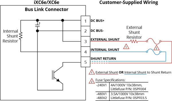
The shunt resistor is used to dissipate excess energy keeping the internal drive voltage within safe levels. The internal shunt resistor is used by connecting the Internal Shunt terminal to an external fuse and then to the Shunt Return terminal. An external resistor if used is connected between the External Shunt and Shunt Return terminals. The external and internal shunt connections cannot be used at the same time. The shunt turn on and off voltages are shown in Internal Shunt Specifications. The drive will turn off if the internal voltage exceeds safe operating levels. The controller parameters ShuntThermalTimeConstant and ShuntNormalizedTemperatureFactor are used to protect the shunt resistor from generating excessive heat. Additional means of protecting an external shunt resistor from overload, such as a thermal shut off switch or fuse is recommended.
DC Bus±:
The DC Bus connection may be used to share the motor supply between multiple drives. This increases efficiency in the case where the regenerative energy from one drive can be used by another. Connection between drives should only be made between drives that share the same motor supply breaker.
DANGER: Shock and Fire Hazard
Electrical wiring must be designed and installed in accordance with local electrical safety regulations to prevent the risk of fire and electrical shock.
The shunt resistor dissipates a high quantity of power. To prevent the danger of electric shock or fire, you must obey the precautions that follow:
- Correctly size, mount, and protect the external shunt resistor.
- Protect the wiring to the internal shunt resistor terminals.
- Do not touch the shunt resistor terminals. There are lethal voltages on the terminals.
- Do not touch the surface of the drive or the external shunt resistor. The temperature can exceed 70°C.
- Restrict access to the shunt resistor while it is connected to a power source.
- Wait 10 minutes after you disconnect power before you access the BUS LINK connector.
- Make sure that the voltage between the DC Bus + and DC Bus - terminals is less than 50 V before you access it.
Table 2-52: Bus Link Connector Pinout
|
Pin |
Description |
Connector |
|---|---|---|
| DC Bus + | Positive motor supply internal voltage (DC link +) |
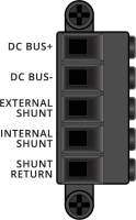
|
| DC Bus - | Negative motor supply internal voltage (DC link -) | |
| External Shunt | Connect an external shunt resistor between this terminal and the Shunt Return terminal | |
| Internal Shunt | To use the internal shunt resistor, connect this terminal to an external fuse. Connect the opposite end of the fuse to the Shunt Return terminal. | |
| Shunt Return | Return connection for the internal or external shunt resistor. |
Table 2-53: Bus Link Mating Connector Ratings
| Specification | Description | |
|---|---|---|
| Type | 5-Pin Terminal Block | |
| Part Numbers | Aerotech: ECK02494 | |
| Phoenix: 1784088 | ||
|
Conductor Cross Section |
One conductor, stranded with ferrule and plastic sleeve | 8...14 AWG (2.5..4 mm2) |
| Two conductors (same cross-section), stranded , twin ferrule with plastic sleeve | 14 AWG (2.5 mm2) | |
| Tightening Torque | 0.3...0.7 N·m | |
| Conductor Insulation Strip Length | 10 mm (3/8 in) | |
|
(1) Refer to the manufacturer website for additional information. |
||
Table 2-54: Internal Shunt Specifications
|
Option |
Description |
Part Numbers Vishay/Dale [Aerotech] |
Turn-On Range (VDC) |
Turn-Off Range (VDC) |
|---|---|---|---|---|
| -240V1 |
50 Ω (min), 300 W |
RBEF030050R00KFBVT |
380 - 395 | 360 - 370 |
|
-480V1, -480V2 |
125 Ω (min), 300 W |
RBEF0300125R0KFBV |
865 - 880 | 815 - 830 |
IMPORTANT: An external fuse must be added in series with the internal shunt when used.
-240V1: 4A/1000V 10x38mm, Littlefuse P/N: 0SPF004
-480V1 and -480V2: 3.5A/1000V 10x38mm, Littlefuse P/N: 0SPF03.5
Table 2-55: Maximum Recommended Shunt Current
|
Peak Current Option |
Value |
|---|---|
|
-10 |
10 A |
|
-20 |
10 A |
|
-30 |
10 A |
|
-50 |
20 A |
|
-100 |
20 A |
Figure 2-38: Bus Link Wiring Schematic
Equation 1:
Calculate the kinetic energy of the system. Any energy that is not lost to the system could be regenerated to the DC bus.
| EM | = [1/2][JM + JL]ꞷ2M | ; rotary motors |
| EM | = [1/2][MM + ML]v2M | ; linear motors |
| Where: | ||
|
JM |
= rotor inertia (kg·m2) | |
|
JL |
= load inertia (kg·m2) | |
|
ꞷM |
= motor speed before deceleration (rad/s) | |
|
MM |
= forcer mass (kg) | |
|
ML |
= load mass (kg) | |
|
vM |
= velocity (m/s) | |
Equation 2:
You will need a shunt resistor if the regenerated energy is greater than the Maximum Additional Storage Energy that the internal bus capacitor can store ( Maximum Additional Storage Energy for a Standard iXC6e/XC6e).
| ECa | = (1/2)· C · (V2M - V2NOM) | |
| Where: | ||
|
C |
= bus capacitor (F) [ |
|
|
VM |
= turn on voltage for shunt circuit (V) [ |
|
|
VNOM |
= nominal bus voltage (V) [ |
|
Table 2-56: Maximum Additional Storage Energy for a Standard iXC6e/XC6e
|
Bus Voltage |
Maximum Additional Energy |
|---|---|
|
320 V |
100.8 J |
| 680 V | 214 J |
If a shunt resistor is required, calculate the value of resistance necessary to dissipate the energy.
Equations 3, 4, and 5:
Calculate the parameters of the shunt resistor.
Equation 3:
| PPEAK | = (EM - ECa) / tD | |
| Where: | ||
|
PPEAK |
= peak power the regeneration circuit must accommodate (W) | |
|
tD |
= deceleration time (s) | |
Equation 4:
| PAV | = (EM - ECa) / tCYCLE | |
| Where: | ||
|
PAV |
= average power dissipated on shunt resistor (W) | |
|
tCYCLE |
= time between deceleration events (s) | |
Equation 5:
| R | = (2VM - VHYS)2 / 4PPEAK | |
| Where: | ||
|
VHYS |
= hysteresis voltage of regeneration circuit (V) [ |
|
Additional useful equations:
| 1 lb·ft | = 1.356 N·m | |
| 1 rad/s | = 9.55 rpm | |