Brushless Motor Connections
The configuration in Brushless Motor Configuration shows a typical brushless motor connection.
Figure 2-9: Brushless Motor Configuration
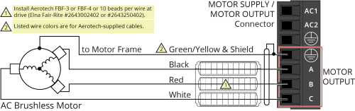
Table 2-9: Wire Colors for Aerotech-Supplied Brushless Motor Cables
|
Pin |
Wire Color Set 1(1) |
Wire Color Set 2 |
Wire Color Set 3 |
Wire Color Set 4 |
|---|---|---|---|---|
|
|
Green/Yellow & Shield (2) |
Green/Yellow & Shield |
Green/Yellow & Shield |
Green/Yellow & Shield |
|
A |
Black |
Blue & Yellow |
Black #1 |
Black & Brown |
|
B |
Red |
Red & Orange |
Black #2 |
Red & Orange |
|
C |
White |
White & Brown |
Black #3 |
Violet & Blue |
|
(1) Wire Color Set #1 is the wire set typically used by Aerotech. (2) “&” indicates two wires (Red & Orange); “ / ” indicates a single wire (Green/White). |
||||

Brushless motors are commutated electronically by the controller. The use of Hall effect devices for commutation is recommended.
The controller requires that the Back-EMF of each motor phase be aligned with the corresponding Hall-effect signal. To ensure proper alignment, motor, Hall, and encoder connections should be verified using one of the following methods: powered, through the use of a test program; or unpowered using an oscilloscope. Both methods will identify the A, B, and C Hall/motor lead sets and indicate the correct connections to the controller. Refer to Brushless Motor Powered Motor and Feedback Phasing for powered motor phasing or Brushless Motor Unpowered Motor and Feedback Phasing for unpowered motor and feedback phasing.
For Aerotech-supplied systems, the motor, encoder and Hall sensors are correctly configured and connection adjustments are not necessary.
A motor filter module such as the MFM10 can be installed between the drive and the motor, which will reduce the level of PWM amplifier related current spikes in the system.