Brushless Motor Unpowered Motor and Feedback Phasing
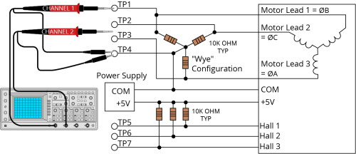
Disconnect the motor from the controller and connect the motor in the test configuration shown in Brushless Motor Phasing Oscilloscope Example. This method will require a two-channel oscilloscope, a 5V power supply, and six resistors (10,000 ohm, 1/4 watt). All measurements should be made with the probe common of each channel of the oscilloscope connected to a neutral reference test point (TP4, shown in Brushless Motor Phasing Oscilloscope Example). Wave forms are shown while moving the motor in the positive direction.
Figure 2-12: Brushless Motor Phasing Oscilloscope Example
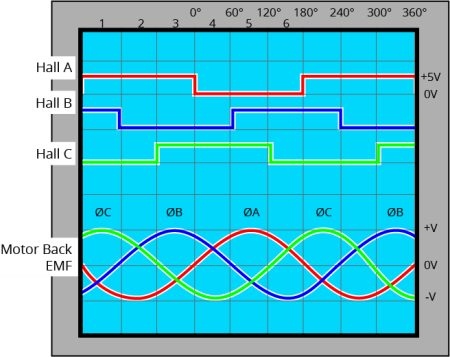
With the designations of the motor and Hall leads of a third party motor determined, the motor can now be connected to an Aerotech system. Connect motor lead A to motor connector A, motor lead B to motor connector B, and motor lead C to motor connector C. Hall leads should also be connected to their respective feedback connector pins (Hall A lead to the Hall A feedback pin, Hall B to Hall B, and Hall C to Hall C). The motor is correctly phased when the Hall states align with the Back EMF as shown in Brushless Motor Phasing Goal. Use the CommutationOffset parameter to correct for Hall signal misalignment.
Figure 2-13: Brushless Motor Phasing Goal