Sine Wave Encoder (Primary) [-MX1 Option]
The Sine Wave Encoder option provides higher positioning resolution by subdividing the fundamental output period of the encoder into smaller increments. The amount of subdivision is specified by the PrimaryEncoderMultiplicationFactor parameter. Use Encoder Tuning to adjust the value of the gain, offset, and phase balance controller parameters to get the best performance. For more information, refer to Automation1 Help.
High resolution or high-speed encoders can require increased bandwidth for correct operation. Use the High Speed Mode of the PrimaryEncoderMultiplierSetup parameter to enable the high bandwidth mode. Because this mode increases sensitivity to system noise, use it only if necessary.
You cannot use a sine wave encoder with the -MX1 multiplier option as an input to the PSO. The -MX1 option does not generate emulated quadrature signals.
For the highest performance, use twisted pair double-shielded cable with the inner shield connected to signal common and the outer shield connected to frame ground. Do not join the inner and outer shields in the cable.
Table 2-19: Sine Wave Encoder Specifications
|
Specification |
Value |
|---|---|
|
Input Frequency (max) |
450 kHz, 2 MHz |
|
Input Amplitude (1) |
0.6 to 1.75 Vpk-pk |
|
Interpolation Factor (max) |
16,384 |
|
Input Common Mode |
1.5 to 3.5 VDC |
|
(1) Measured as SIN(+) - SIN(-) or COS(+) - COS(-) |
|
Figure 2-22: Sine Wave Encoder Phasing Reference Diagram
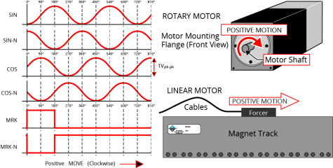
Figure 2-23: Sine Wave Encoder Schematic (Feedback Connector)
