Motor Supply Connector (-AC Option)
Motor power is applied to the AC1 and AC2 terminals of the Motor Supply connector.
Peak Current Option -10: The AC1 input is internally connected to a 5 A fuse.
Peak Current Option -20: The AC1 input is internally connected to a 10 A fuse.
Refer to Fuse Specifications for the internal fuse part numbers.
The AC2 input is not internally fused. The system designer must provide external circuit breaker(s) in accordance with local electrical safety requirements. D-type breakers are required for proper branch protection (refer to Electrical Specifications). Individual circuit breakers could be required for each drive in a system. The size of the breaker required is dependent upon the gauge of wire used between the drive and the motor.
For CE compliance, connect an AC line filter as close as possible to the drive (refer to Minimizing Noise for EMC/CE Compliance).
WARNING: Verify that all ground connections are installed correctly before you apply power to the iXA4/XA4.
Figure 2-2: Motor Supply Connections
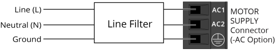
Table 2-3: Motor Supply Connector Pinout
| Pin | Description |
|---|---|
|
AC1 |
AC Motor Power Input |
|
AC2 |
AC Motor Power Input |
|
|
Protective Earthing Conductor - 2.5 mm2 / 14 AWG min conductor size |

Table 2-4: Motor Supply Mating Connector Ratings
| Specification | Description | |
|---|---|---|
| Type | 3-Pin Terminal Block | |
| Part Numbers | Aerotech: ECK02388 | |
| Phoenix: 1756272 | ||
|
Conductor Cross Section |
One conductor, stranded with ferrule and plastic sleeve | 14...22 AWG (0.25...2.5 mm2) |
| Two conductors (same cross-section), stranded, twin ferrule with plastic sleeve | 16...20 AWG (0.5...1.5 mm2) | |
| Tightening Torque | 0.5...0.6 N·m | |
| Conductor Insulation Strip Length | 7 mm (0.25 in) | |
|
(1) Refer to the manufacturer website for additional information. |
||
Use these parameters to configure motor overload protection: AverageCurrentThreshold, AverageCurrentTime, and MaxCurrentClamp.