Motor Power Output Connector
The drive can be used to control the following motor types:
- Aerotech Brushless Hexapod Motors
For a complete list of electrical specifications, refer to Electrical Specifications
DANGER: Shock and Fire Hazard
Electrical wiring must be designed and installed in accordance with local electrical safety regulations to prevent the risk of fire and electrical shock.
Table 2-8: Motor Power Output Connector Pinout
|
Pin # |
Description |
Connector |
|---|---|---|
| 13 | Earth Ground |
|
| 14 | Motor Phase A (Axis 1) | |
| 2 | Motor Phase B (Axis 1) | |
| 15 | Motor Phase C (Axis 1) | |
| 1 | Motor Ground (Axis 1) | |
| 16 | Motor Phase A (Axis 2) | |
| 4 | Motor Phase B (Axis 2) | |
| 17 | Motor Phase C (Axis 2) | |
| 3 | Motor Ground (Axis 2) | |
| 18 | Motor Phase A (Axis 3) | |
| 6 | Motor Phase B (Axis 3) | |
| 19 | Motor Phase C (Axis 3) | |
| 5 | Motor Ground (Axis 3) | |
| 20 | Motor Phase A (Axis 4) | |
| 8 | Motor Phase B (Axis 4) | |
| 21 | Motor Phase C (Axis 4) | |
| 7 | Motor Ground (Axis 4) | |
| 22 | Motor Phase A (Axis 5) | |
| 10 | Motor Phase B (Axis 5) | |
| 23 | Motor Phase C (Axis 5) | |
| 9 | Motor Ground (Axis 5) | |
| 24 | Motor Phase A (Axis 6) | |
| 12 | Motor Phase B (Axis 6) | |
| 25 | Motor Phase C (Axis 6) | |
| 11 | Motor Ground (Axis 6) |
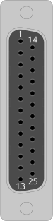
Table 2-9: Feedback Mating Connector Ratings
| Specification | 25-Pin Solder Cup |
Backshell |
|---|---|---|
| Aerotech Part Number | ECK00101 | ECK00656 |
| Amphenol Part Number (1) | DB25P064TXLF |
17E-1726-2 |
| Maximum Wire Size | 20 AWG (0.5 mm2) |
N/A |
|
(1) Refer to the manufacturer website for additional information. |
||