Installation Overview
This image shows the order in which to make connections and settings that are typical to the GL4. If a custom interconnect drawing was supplied with your system, that drawing is on your Storage Device and shows as a line item on your Sales Order in the Integration section.
Figure: Installation Connection Overview
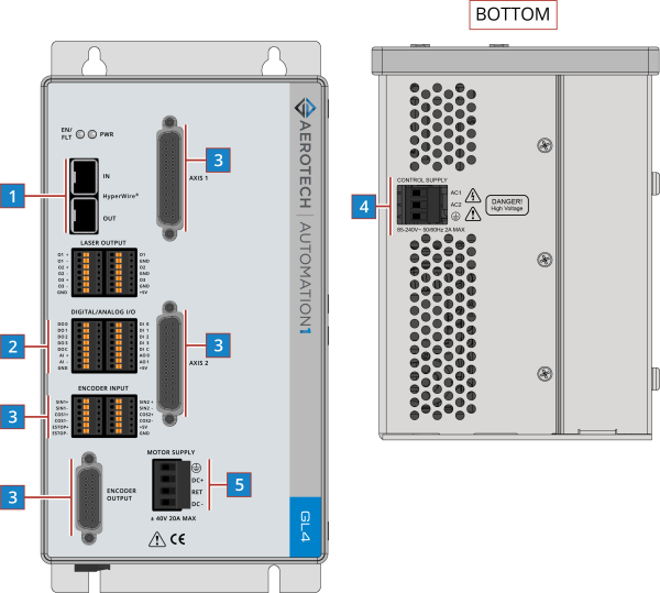
| 1 |
Connect a PC HyperWire port to an amplifier HyperWire port. |
|
| 2 |
Connect the Digital/Analog I/O. |
|
| 3 |
Connect to Axis 1 and Axis 2 motor and feedback connectors. |
|
| 4 |
Connect to the Control Supply connector. |
|
| 5 |
Connect to the Motor Supply connector. |