Installation Overview
The images that follow show the order in which to make connections and settings that are typical to the GI4. If a custom interconnect drawing was supplied with your system, that drawing is on your Storage Device and shows as a line item on your Sales Order in the Integration section.
Figure: Installation Connection Overview (Standard)
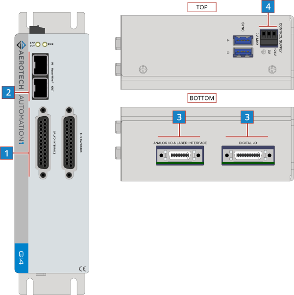
| 1 |
Connect the galvo scanner to the Galvo Interface connector. |
|
| 2 |
Connect the PC HyperWire to the HyperWire In port. |
|
| 3 |
Connect the laser interface input and additional I/O as required by your application. |
|
| 4 |
Connect the power supply to the Control Supply. |
Figure: Installation Connection Overview (OEM)

| 1 |
Connect the galvo scanner to the Galvo Interface connector. |
|
| 2 |
Connect the PC HyperWire to the HyperWire In port. |
|
| 3 |
Connect the laser interface input and additional I/O as required by your application. |
|
| 4 |
Connect the power supply to the Control Supply. |