Galvo Interface Connector
The Galvo Interface connector supports two- and three-axis XY2-100 and XY3-100 galvo scanners. It outputs galvo clock, sync, and channel connections. You will need an interconnect cable to connect the GI4 to a galvo that supports these interfaces (refer to Standard Galvo Interconnection Cables for standard Aerotech interconnect cables). Use shielded cables.
Many galvo scanner suppliers use the "no connection" pins on their interconnect cables to supply power to the scanner. Consult the hardware manual of the scanner to determine which pins are used to supply power and modify the interconnect cable accordingly.
Table 2-3: Galvo Interface Pinout
|
Pin # |
Description |
In/Out/Bi |
Connector |
|---|---|---|---|
|
1 |
Reserved |
N/A |
|
|
2 |
Reserved |
N/A |
|
|
3 |
Signal Common |
Output | |
|
4 |
Reserved |
N/A | |
|
5 |
Channel 3+ | Output | |
|
6 |
Sync+ | Output | |
|
7 |
Reserved |
N/A | |
|
8 |
+5 V Supply (500 mA) | Output | |
|
9 |
Channel 1+ | Output | |
|
10 |
Channel 2+ | Output | |
| 11 |
Reserved |
N/A | |
|
12 |
Clock+ | Output | |
|
13 |
Reserved | N/A | |
|
14 |
Reserved |
N/A | |
|
15 |
Reserved |
N/A | |
|
16 |
Reserved |
N/A | |
|
17 |
Reserved |
N/A | |
|
18 |
Channel 3- | Output | |
| 19 |
Sync- |
Output | |
|
20 |
Reserved |
N/A | |
|
21 |
Signal Common | Output | |
|
22 |
Channel 1- | Output | |
|
23 |
Channel 2- | Output | |
|
24 |
Reserved | N/A | |
|
25 |
Clock- | Output |
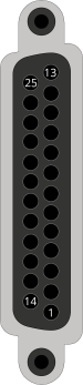
Table 2-4: Galvo Interface Mating Connector Ratings
| Specification | 25-Pin Solder Cup |
Backshell |
|---|---|---|
| Aerotech Part Number | ECK00101 | ECK00656 |
| Amphenol Part Number (1) | DB25P064TXLF |
17E-1726-2 |
| Maximum Wire Size | 20 AWG (0.5 mm2) |
N/A |
|
(1) Refer to the manufacturer website for additional information. |
||
Table 2-5: Standard Galvo Interconnection Cables
| Cable P/N |
Description |
|---|---|
| C22281-XX |
GI4 to XY2-100 Galvo with Power 25D-25D-MAX80DM |
| C23931-XX |
GI4 to XY2-100 Galvo without Power 25D-25D-MAX100DM |
| C22282-XX | C22282 - GI4 to XY3-100 Galvo with Power 25D-25D-MAX80DM |
| C23932-XX | C23932 - GI4 to XY3-100 Galvo without Power 25D-25D-MAX100DM |