PSO Input Frequency Specifications
PSO supports a maximum input frequency of 100 MHz. But the type of incremental position feedback signals that you are tracking and how these inputs are connected to your drive have an effect on the maximum input frequency. To see how different operations change the maximum input frequency limits, refer to the table that follows.
Table: PSO Input Frequency Limits
| Operation | Limit (million counts per second) | Cause |
Documentation |
|---|---|---|---|
|
40 |
The maximum supported encoder input frequency is 10 MHz, which is 40 million counts per second |
Drive hardware manuals (see Manuals & Help Files online) |
|
100 |
Emulated quadrature signals in the drive that are generated from the sine wave signals can be up to 100 MHz |
PrimaryEmulatedQuadratureDivider Parameter or AuxiliaryEmulatedQuadratureDivider Parameter |
|
25 |
The maximum supported frequency for the Drive Encoder Output feature is 25 MHz |
Configuring the Drive Encoder Output section on the Device Functions page |
|
95 |
The maximum frequency for the pulse stream feature is 95 MHz |
Pulse Stream section on the Device Functions page |
Sine Wave Encoder Recommendations
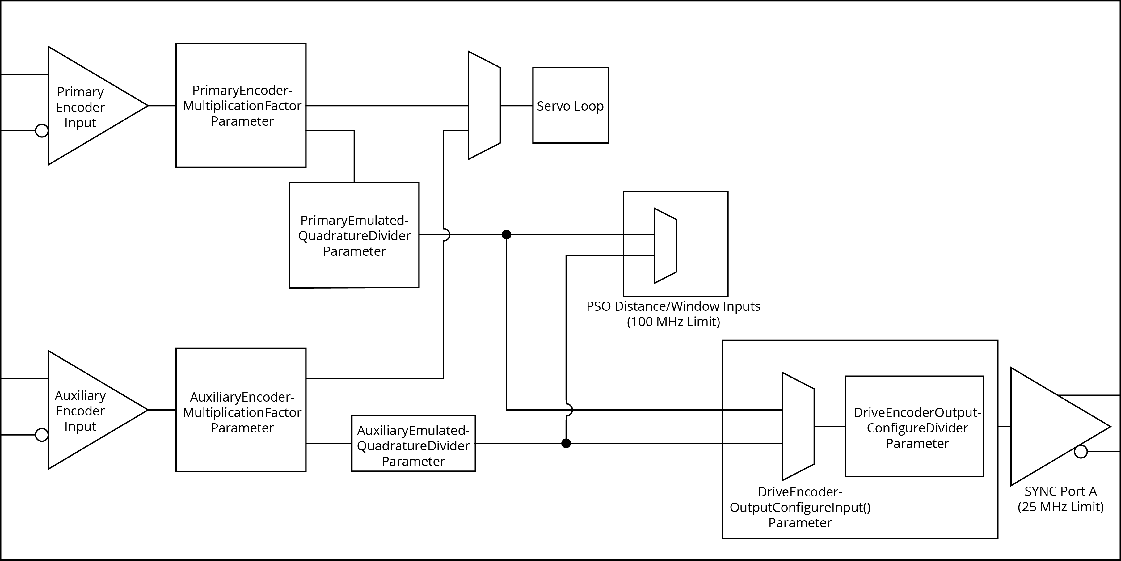
When you are tracking a sine wave primary or auxiliary input, or an absolute encoder with sine wave incremental signals, you can use the PrimaryEmulatedQuadratureDivider Parameter and the AuxiliaryEmulatedQuadratureDivider Parameter to limit the frequency of the signals. These parameters are applied to the emulated quadrature signals that are used for PSO and for the Drive Encoder Output features. Aerotech recommends that if you configure PSO and Drive Encoder Output to track feedback signals from a sine wave encoder, you only use the PrimaryEmulatedQuadratureDivider parameter or the AuxiliaryEmulatedQuadratureDivider parameter to obey the frequency limits of both PSO (100 MHz) and Drive Encoder Output (25 MHz). If a higher PSO input frequency is necessary, you can use these parameters to limit the feedback signals to 100 MHz, and then use the DriveEncoderOutputConfigureDivider() AeroScript function to divide the feedback velocity more, to a maximum of 25 MHz. See the diagram that follows. For more information about DriveEncoderOutputConfigureDivider(), see Configuring the Drive Encoder Output.
MX Quadrature Warnings and Errors
High-frequency changes in the velocity of the axis can cause the rate of quadrature generation to exceed the maximum allowable limit, even if the commanded velocity is within limits. This occurs because the quadrature generation for sine wave encoder signals is faster than the data collection rate of the drive.
Use the MxQuadratureWarning and MxQuadratureError status items in the AuxililaryFeedbackStatus and PrimaryFeedbackStatus enums to identify if the axis is violating the maximum quadrature generation rate. See AeroScript Enums. The descriptions of these status items are as follows:
-
MxQuadratureWarning: The axis is violating the maximum allowable quadrature generation rate. The controller can momentarily buffer extra encoder counts, but while the buffer is doing this, quadrature generation is delayed. -
MxQuadratureError: Encoder counts are lost because the buffer inMxQuadratureWarningis full and overflowed.


