Galvo and IFOV Functions
IMPORTANT: Galvo and IFOV functionality are available only when you use a PC-based controller.
Automation1 has galvo marking capabilities when used with the GI4 or GL4 hardware. The GI4 and GL4 are galvo drives that control a galvo scanner. You can issue motion to any galvo axis by using the motion functions in the controller such as MoveRapid(), MoveLinear(), MoveCw(), MoveCcw(), and MoveDelay().
This topic includes the galvo and Infinite Field of View (IFOV) functions that are available in the AeroScript API.
- The galvo functions let you configure and control the laser and also configure advanced galvo-specific features.
- The IFOV functions supply seamless marking over a field of view that is larger than the field of view of the galvo scan head. The controller combines the motion of the galvo scan head with the motion of traditional servo axes to extend the field of view of the galvo scan head.
WARNING: The GI4 and GL4 can control a laser scan system. When you install and use one of these galvo drives, obey all laser safety rules. You are responsible for the laser safety of your system.
Configure the Laser
The laser configuration commands specify the behavior of the three laser output signals of the GI4 or GL4. For more information about the signals, refer to the hardware manual for your galvo drive. The laser output signals are on the Laser Interface connector of the GI4 and the Laser Output connector of the GL4. You must use the functions in this section to configure the laser before you can command the laser in your AeroScript program.
When you issue the GalvoConfigureLaserMode() function, the changes to the laser configuration are sent to your GI4 or GL4. Instructions about how to use the GalvoConfigureLaserMode() are listed below.
function GalvoConfigureLaserMode($axis as axis, $laserMode as integer)
Specifies the mode in which the laser output signals operate.
Arguments
$axis The axis on which to configure the laser mode.
$laserMode The value of the laser output mode.
WARNING: Do not issue the GalvoConfigureLaserMode() function when the laser is being commanded to fire.
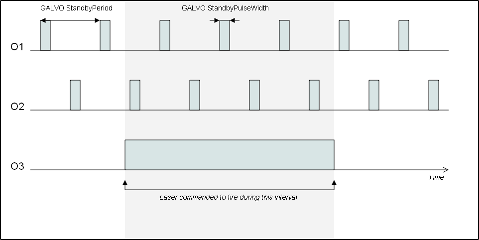
Use this function to select the mode in which the laser output signals operate. When the laser is being commanded to fire, O3 is active. When the laser is not being commanded to fire, O3 is not active. To set the active polarity (for RS-422 outputs) and transistor state (for opto-isolated outputs) of the laser output signals, use the switch on the GL4. You cannot configure the active polarity on the GI4. For more information, refer to the hardware manual for your drive.
- Based on the type of laser that you have and how the laser operates, select the correct laser mode. For more information about how different types of lasers apply to different laser modes, refer to the Typical Application and the Description columns of the table listed below.
- In your AeroScript program, type all the configuration functions that are applicable to your laser mode and give the correct values to their arguments. Refer to the Related Functions column of the table listed below.
- In your AeroScript program, issue the GalvoConfigureLaserMode() function and give the correct values to all arguments. Make sure the value for $laserMode is the laser mode that you want to use.
- Run your AeroScript program to activate the laser mode. All of the laser configuration information is sent to the controller and the new laser mode is immediately active.
IMPORTANT: For the laser output to activate, you must enable all the axes of your galvo drive. Make sure to include axes that do not engage in marking motion.
The table that follows shows the possible values for the $laserMode argument. Before you issue GalvoConfigureLaserMode(), you must configure the applicable functions in the Related Functions column of the table.
Table: $laserMode Argument Values
|
Value |
Typical Application |
Description |
Related Functions |
|---|---|---|---|
|
0 |
CO2 laser |
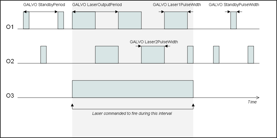
When the laser is firing, O1 and O2 are modulation signals with a configurable frequency and a fixed 180° phase shift. You can independently specify the O1 and O2 pulse widths. When the laser is not firing and you use the GalvoConfigureStandbyPeriod() and GalvoConfigureStandbyPulseWidth() functions to specify a standby period and pulse width, O1 and O2 output standby pulses. When the laser is not firing and you do not specify a standby period and pulse width, O1 and O2 are not active. |
GalvoConfigureLaserOutputPeriod() GalvoConfigureLaser1PulseWidth() GalvoConfigureLaser2PulseWidth() GalvoConfigureStandbyPeriod() GalvoConfigureStandbyPulseWidth() |
|
1 |
YAG laser |
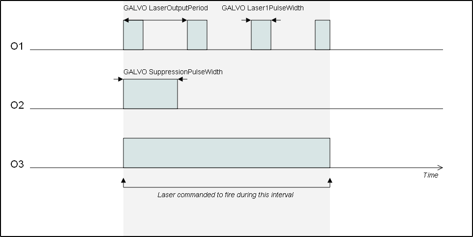
O2 is a suppression pulse that is output when the laser starts firing. When the laser is firing, O1 is a periodic signal with a configurable frequency and pulse width. When the laser is not firing, O1 and O2 are not active. |
GalvoConfigureLaserOutputPeriod() GalvoConfigureLaser1PulseWidth() GalvoConfigureSuppressionPulseWidth() |
|
2 |
YAG laser |
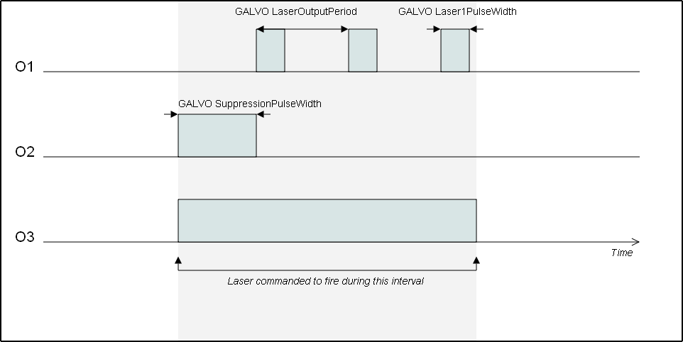
O2 is a suppression pulse that is output when the laser starts firing. O1 does not become active until the suppression pulse stops. While the laser is firing, O1 is a periodic signal with a configurable frequency and pulse width. When the laser is not firing, O1 and O2 are not active. |
GalvoConfigureLaserOutputPeriod() GalvoConfigureLaser1PulseWidth() GalvoConfigureSuppressionPulseWidth() |
|
3 |
YAG laser |
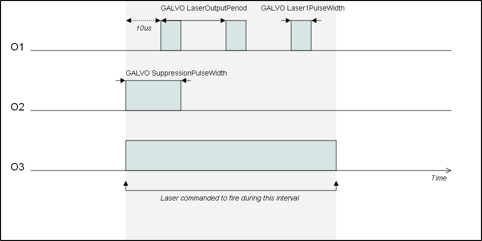
O2 is a suppression pulse that is output when the laser starts firing. 10us after the start of the suppression pulse, O1 becomes active. When the laser is firing, O1 is a periodic signal with a configurable frequency and pulse width. When the laser is not firing, O1 and O2 are not active. |
GalvoConfigureLaserOutputPeriod() GalvoConfigureLaser1PulseWidth() GalvoConfigureSuppressionPulseWidth() |
|
4 |
General Purpose |
O1 and O2 are standby signals with a configurable frequency and pulse width. They have a fixed 180° phase shift. When the laser is firing, O1 and O2 are active. When the laser is not firing, O1 and O2 are still active. |
GalvoConfigureStandbyPeriod() GalvoConfigureStandbyPulseWidth() |
When the GalvoConfigureLaserMode() function executes, the laser interface disables while the new configuration information loads. All three laser output signals become inactive.
function GalvoConfigureLaser1PulseWidth($axis as axis, $time as real)
Specifies the pulse width, in microseconds, of the O1 signal.
Arguments
$axis The axis on which to configure the laser 1 pulse width.
$time The time value in microseconds.
Use GalvoConfigureLaser1PulseWidth() to specify the pulse width in microseconds of the O1 signal. This function applies only in laser modes 0, 1, 2, and 3 of the GalvoConfigureLaserMode() function.
The $time argument has a resolution of 0.01 microseconds and a maximum value of 42.9 seconds. If you specify a time that has a resolution that the GI4 or GL4 does not support, the controller rounds to the nearest supported value.
function GalvoConfigureLaser2PulseWidth($axis as axis, $time as real)
Specifies the pulse width, in microseconds, of the O2 signal.
Arguments
$axis The axis on which to configure the laser 2 pulse width.
$time The time value in microseconds.
Use GalvoConfigureLaser2PulseWidth() to specify the pulse width in microseconds of the O2 signal. This function applies only in laser mode 0 of the GalvoConfigureLaserMode() function.
The $time argument has a resolution of 0.01 microseconds and a maximum value of 42.9 seconds. If you specify a time that has a resolution that the GI4 or GL4 does not support, the controller rounds to the nearest supported value.
function GalvoConfigureLaserOutputPeriod($axis as axis, $time as real)
Specifies the period, in microseconds, of the O1 and O2 signals.
Arguments
$axis The axis on which to configure the laser output period.
$time The time value in microseconds.
Use GalvoConfigureLaserOutputPeriod() to specify the period in microseconds of the O1 signal and the O2 signal in laser mode 0. This function applies only in laser modes 0, 1, 2, and 3 of the GalvoConfigureLaserMode() function.
The $time argument has a resolution of 0.01 microseconds and a maximum value of 42.9 seconds. If you specify a time that has a resolution that the GI4 or GL4 does not support, the controller rounds to the nearest supported value.
function GalvoConfigureStandbyPeriod($axis as axis, $time as real)
Specifies the period, in microseconds, of the standby signals.
Arguments
$axis The axis on which to configure the standby period.
$time The time value in microseconds.
Use GalvoConfigureStandbyPeriod() to specify the period in microseconds of the standby signals. This function applies only in laser modes 0 and 4 of the GalvoConfigureLaserMode() function.
The $time argument has a resolution of 0.01 microseconds and a maximum value of 42.9 seconds. If you specify a time that has a resolution that the GI4 or GL4 does not support, the controller rounds to the nearest supported value.
function GalvoConfigureStandbyPulseWidth($axis as axis, $time as real)
Specifies the pulse width, in microseconds, of the standby signals.
Arguments
$axis The axis on which to configure the standby pulse width.
$time The time value in microseconds.
Use the GalvoConfigureStandbyPulseWidth() function to specify the pulse width in microseconds of the standby signals. This function applies only in laser modes 0 and 4 of the GalvoConfigureLaserMode() function.
The $time argument has a resolution of 0.01 microseconds and a maximum value of 42.9 seconds. If you specify a time that has a resolution that the GI4 or GL4 does not support, the controller rounds to the nearest supported value.
function GalvoConfigureSuppressionPulseWidth($axis as axis, $time as real)
Specifies the pulse width, in microseconds, of the suppression signal.
Arguments
$axis The axis on which to configure the suppression pulse width.
$time The time value in microseconds.
Use the GalvoConfigureSuppressionPulseWidth() function to specify the pulse width in microseconds of the suppression signal. This function applies only in laser modes 1, 2, and 3 of the GalvoConfigureLaserMode() function.
The $time argument has a resolution of 0.01 microseconds and a maximum value of 42.9 seconds. If you specify a time that has a resolution that the GI4 or GL4 does not support, the controller rounds to the nearest supported value.
Configure Laser Delays
You can use the GalvoConfigureLaserDelays() function to specify when the GI4 or GL4 starts or stops firing the laser based on when the laser is commanded to power on or off.
function GalvoConfigureLaserDelays($axis as axis, $onDelay as real, $offDelay as real)
Specifies when the axis fires the laser relative to when you command the laser to power on and when the axis stops firing the laser relative to when you command the laser to power off.
Arguments
$axis The axis on which to configure laser delays.
$onDelay The delay time, in microseconds, that is necessary for the laser to power on. If your program uses the automatic laser mode, this value must be greater than or equal to -32,768 and less than or equal to 32,767. If your program uses the manual laser mode or if you are operating in IFOV mode, this value must be greater than or equal to -975 and less than or equal to 32,767.
$offDelay The delay time, in microseconds, that is necessary for the laser to power off. This value must be greater than or equal to -975 and less than or equal to 2,000,000.
You must specify both a laser on delay and a laser off delay.
Laser On Delay
The $onDelay argument specifies when the GI4 or GL4 fires the laser relative to when you command the laser to power on. The delay can be a positive value, negative value, or zero. You can use a positive delay to prevent non-uniform marking while the mirrors accelerate to the marking speed. You can use a negative delay to mark a material that the laser must preheat before a marking move occurs.
If your AeroScript program uses the automatic laser mode, a positive delay powers on the laser after the start of a marking move sequence containing MoveLinear(), MoveCw(), or MoveCcw() moves. A negative delay powers on the laser before the start of a marking move sequence. Negative delays extend the total quantity of time of the marking move sequence because the delays occur before the marking move starts. A positive delay does not extend the total quantity of time of the marking move sequence. To use the automatic laser mode, refer to the GalvoLaser.Auto setting in the GalvoLaserOutput() function.
If your AeroScript program uses the manual laser mode, a positive delay powers on the laser after you manually turn on the laser, and a negative delay powers on the laser before you manually turn on the laser. Positive and negative delays do not extend the total quantity of time of the marking move sequence. To use the manual laser mode, refer to the LaserOutputSet() function.
Laser Off Delay
The $offDelay argument specifies when the GI4 or GL4 stops firing the laser relative to when you command the laser to power off. The delay can be a positive value, negative value, or zero. You can use a positive delay to keep the laser on while the scanner goes into position. You can use a negative delay to prevent the laser from supplying too much energy at the end of a deceleration.
If your AeroScript program uses the automatic laser mode, a positive delay powers off the laser after the end of a marking move sequence containing MoveLinear(), MoveCw(), or MoveCcw() moves. A negative delay powers off the laser before the end of a marking move sequence. To use the automatic laser mode, refer to the GalvoLaser.Auto setting in the GalvoLaserOutput() function.
If your AeroScript program uses manual laser mode, a positive delay powers off the laser after you manually turn off the laser, and a negative delay powers off the laser before you manually turn off the laser. To use the manual laser mode, refer to the LaserOutputSet() function.
More Information
- For laser delays to operate correctly, you must set the MotionUpdateRate Parameter to a value that is greater than or equal to 10 kHz. The recommended value is 100 kHz.
- The $onDelay and $offDelay values must both be less than the minimum time between laser pulses. The time between laser pulses is the duration of a marking move sequence (laser on time) added to the duration of a non-marking move sequence (laser off time). If either delay time argument is more than the time between laser pulses, the drive might not fire the laser at each pulse sequence.
- The time of a marking move sequence is determined by dividing the marking distance by the average speeds of the moves.
- The time of a non-marking move sequence is determined by dividing the non-marking distance by the average speeds of the moves.
Automatic Laser Control
IMPORTANT: Before you can use the laser, you must configure the laser as described in the Configure the Laser section.
When doing galvo motion, moves are referred to as marking moves or non-marking moves. Marking moves have the laser powered on during the whole move. Non-marking moves have the laser powered off during the move. Marking moves include all coordinated moves: MoveLinear(), MoveCcw(), and MoveCw(), and non-marking moves include all other move types.
To automatically turn the laser on or off depending on if the move is marking or non-marking, the controller supports automatic laser mode. By default, after a controller reset, all galvo axes are in automatic laser mode. You can enable automatic laser mode by using the GalvoLaser.Auto enum with the GalvoLaserOutput() function.
IMPORTANT: Automatic laser mode is available only on galvo drives.
| enum GalvoLaser
Off = 0 On = 1 Auto = 2 end |
function GalvoLaserOutput($axis as axis, $laserState as GalvoLaser)
Specifies how the laser on a galvo axis is controlled.
Arguments
$axis The axis on which to configure the laser state.
$laserState The mode to use to control the laser.
To disable automatic laser mode and manually control the laser synchronized with motion, you can use the LaserOutputSet() or the GalvoLaserOutput() function. For more information, refer to Laser Output.
Laser delays have different behaviors in automatic and manual laser mode. Refer to GalvoConfigureLaserDelays() for more information.
IMPORTANT: Aerotech recommends that you set the MotionUpdateRate Parameter equal to the position update rate of the drive to more accurately synchronize the laser to the start or end of a move than at lower motion update rates.
More Information
-
All axes of a galvo drive must be enabled for the laser to turn on during automatic or manual laser mode.
-
If you abort motion on
Configure Galvo Calibration
To compensate for optical effects of the galvo head and lens, you must configure Galvo 2D Axis Calibration for your marking patterns to be correct. You can edit the Galvo 2D Axis Calibration configuration in the Configure workspace on the Calibration tab in the Controller category.
Optimize Laser Power
If you want the controller to change the power of the laser based on the position of the two galvo axes, use Galvo Power Correction. You can edit the Galvo Power Correction configuration in the Configure workspace on the Calibration tab in the Controller category.
Advanced Features
The functions that follow provide additional advanced configuration functionality for the GI4 or GL4.
function GalvoEncoderScaleFactorSet($axis as axis, $encoderScaleFactor as real)
Enables "marking on the fly" functionality.
Arguments
$axis The axis on which to configure the encoder scale factor.
$encoderScaleFactor The ratio of scanner counts to encoder counts. This value must be greater than -32,768 and less than 32,767.
Use GalvoEncoderScaleFactorSet() to enable "marking on the fly" functionality on the specified axis of the GI4 or GL4. This feature lets the drive monitor the position of an external encoder. The drive adjusts the position of the scanner to compensate for changes in the external position.
You can use "marking on the fly" functionality in many applications. For example, you might want to draw a pattern on a part that is continuously moving through the field of view of the scanner during the marking process (the part might be on a conveyor belt).
For the GI4 or GL4 to correctly adjust the position of the scanner, you must specify the ratio of scanner counts to encoder counts. Specify this ratio to the $encoderScaleFactor argument. If encoder adjustment is being applied to two GI4 or GL4 axes, then you must issue this function twice (one time for each axis). If you need to change the $encoderScaleFactor argument after this function was issued, you must first issue GalvoEncoderScaleFactorSet() with a value of 0.0. If you do not zero the scale factor first, the controller step changes the position command, which causes a large current increase in the motor. You can use a different scale factor in each function. Specify a value greater than -32,768 and less than 32,767 for $encoderScaleFactor.
When the GalvoEncoderScaleFactorSet() function executes, the external position counter for the specified axis clears and encoder adjustment starts at the current position of the scanner.
To deactivate "marking on the fly" on an axis, issue this function with $encoderScaleFactor set to 0.0. If encoder adjustment is being applied to two GI4 or GL4 axes, then you must issue this function two times, in order to deactivate the feature on both axes.
function GalvoProjectionSetCoefficients($axis as axis, $coefficients[9] as real)
Specifies the projective transformation coefficients that are applied to galvo axes.
Arguments
$axis The galvo axis on which the projection is to be applied.
$coefficients The coefficients to use.
Use the GalvoProjectionSetCoefficients() function to set the projective transformation coefficients that are applied on the GL4. After you specify the coefficients, use the GalvoProjectionOn() and GalvoProjectionOff() functions to enable and disable the transformation.
function GalvoProjectionOn($axis as axis)
Enables the projective transformation on galvo axes.
Arguments
$axis The galvo axis on which to apply the projection.
Use the GalvoProjectionOn() function to enable the projective transformation on the GL4.
function GalvoProjectionOff($axis as axis)
Disables the projective transformation on galvo axes.
Arguments
$axis The galvo axis on which to disable the projection.
Use the GalvoProjectionOff() function to disable the projective transformation on the GL4.
function GalvoRotationSet($axis as axis, $angle as real)
Specifies an angle of rotation that is applied to galvo axes.
Arguments
$axis The galvo axis on which the rotation is to be applied.
$angle The angle in degrees.
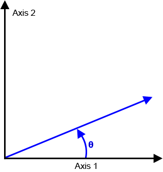
Use the GalvoRotationSet() function to specify a rotation that is applied to the first two axes of the GI4 or GL4. When you operate the controller in Infinite Field of View mode, you can use this function to correct mechanical alignment errors that occur between the galvo and servo axes. Use this function only to correct misalignment errors that occur between these axes. If you want to rotate the programmed part, refer to Transformation Functions instead.
The GalvoRotationSet() rotation is applied relative to the center of travel of the galvo axes. If you specify x as the first axis of the GI4 or GL4 and y as the second axis, use the equation that follows to calculate the rotation.
xrotated = xcos(ϴ) - ysin(ϴ)
yrotated = xsin(ϴ) - ycos(ϴ)
function GalvoWobbleSetConfiguration($axis as axis, $amplitudeParallel as real, $amplitudePerpendicular as real, $frequency as real, $wobbleMode as GalvoWobbleMode, $wobbleType as GalvoWobbleType)
Configures the wobble feature, which generates a wobble pattern that is added to the motion command of a galvo axis.
Arguments
$axis The galvo axis on which the galvo wobble is to be applied.
$amplitudeParallel The amplitude of the wobble shape parallel to the vector path.
$amplitudePerpendicular The amplitude of the wobble shape perpendicular to the vector path.
$frequency The frequency of the wobble oscillation. Specified in hertz for time-based mode or user units for distance-based mode.
$wobbleMode Specifies whether the wobble is repeated based on a fixed time or a fixed vector distance.
$wobbleType The type of figure that is generated by the wobble.
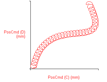
Use the GalvoWobbleSetConfiguration() function to configure the galvo wobble feature. When the GI4 or GL4 does marking motion, the galvo wobble feature generates an oscillatory pattern and the controller combines that pattern with the position command of the drive. The oscillatory pattern increases the width of the marking line.
Set the $amplitudePerpendicular argument to control the width of the marking line. Set the $amplitudeParallel argument with the $frequency argument to control the overlap that occurs between each wobble oscillation.
Wobble Mode
Set the $wobbleMode argument to control if the $frequency of the repeated wobble pattern is time-based or distance-based. When you use time-based mode, the controller repeats the wobble pattern at a fixed time interval. When you use distance-based mode, the controller repeats the wobble pattern at a fixed distance. In distance-based mode, the speed of the marking vector controls the time at which the controller repeats the wobble pattern. To create a uniform overlap of the wobble pattern during acceleration![]() The change in velocity as a function of time. and deceleration, Aerotech recommends that you use the distance-based mode.
The change in velocity as a function of time. and deceleration, Aerotech recommends that you use the distance-based mode.
Table: Galvo Wobble Mode Values
|
Value |
Name |
Description |
|---|---|---|
|
GalvoWobbleMode.TimeBased |
TimeBased |
Wobble is repeated at a fixed time interval |
|
GalvoWobbleMode.DistanceBased |
DistanceBased |
Wobble is repeated at a fixed vector |
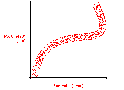
Wobble Type
Set the $wobbleType argument to control the type of wobble pattern that the controller generates.
Table: Galvo Wobble Type Values
|
Value |
Name |
Description |
|---|---|---|
|
GalvoWobbleType.Ellipse |
Ellipse |
An ellipse shape |
|
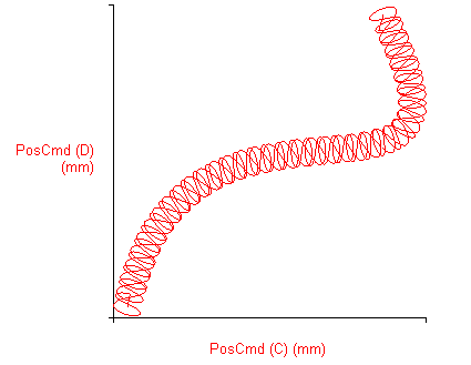
GalvoWobbleType.Figure8Parallel |
Figure8Parallel |
A figure 8 shape parallel to the vector path |
|
GalvoWobbleType.Figure8Perpendicular |
Figure8Perpendicular |
A figure 8 shape perpendicular to the vector path |
Refer to the figures that follow for the different WobbleType patterns.
function GalvoWobbleOn($axis as axis)
Enables the galvo wobble feature.
Arguments
$axis The galvo axis on which the galvo wobble is to be applied.
Use the GalvoWobbleOn() function to enable the galvo wobble feature that was previously configured with GalvoWobbleSetConfiguration(). When you enable the galvo wobble feature, the controller combines the wobble motion with the marking motion.
function GalvoWobbleOff($axis as axis)
Disables the galvo wobble feature.
Arguments
$axis The galvo axis on which the galvo wobble is to be disabled.
Use this function to disable the galvo wobble feature.
Infinite Field of View (IFOV)
Infinite Field of View (IFOV) supplies seamless marking over a field of view that is larger than the field of view of the galvo scan head. Automation1 combines the motion of the galvo scan head of the GI4 or GL4 with the motion of traditional servo axes to extend the field of view of the galvo scan head.
When you program motion to the galvo scan head over an extended field of view, the controller automatically commands motion to the servo and galvo axes. The controller maintains the high throughput of the galvo axes and the extended travel of the servo axes.
Examples, procedures, and some information in the IFOV topics use these axis configurations:
- X and Y are servo axes.
- A and B are galvo axes.
- X and A move in the same direction.
- Y and B move in the same direction.
IMPORTANT: Before you can use IFOV, you must set the
function IfovSetAxisPairs($axisPairH[] as axis, $axisPairV[] as axis)
Configures axes to command in Infinite Field of View (IFOV).
Arguments
$axisPairH The horizontal axis pair. This pair consists of a galvo axis and its corresponding servo axis.
$axisPairV The vertical axis pair. This pair consists of a galvo axis and its corresponding servo axis.
function IfovSetAxisPairs($axisPairH[] as axis, $axisPairV[] as axis, $scaleFactorH as real, $scaleFactorV as real)
Configures axes to command in Infinite Field of View (IFOV).
Arguments
$axisPairH The horizontal axis pair. This pair consists of a galvo axis and its corresponding servo axis.
$axisPairV The vertical axis pair. This pair consists of a galvo axis and its corresponding servo axis.
$scaleFactorH Specifies the scaling from the servo axis to the galvo axis in the horizontal axis pair.
$scaleFactorV Specifies the scaling from the servo axis to the galvo axis in the vertical axis pair.
Use this function to specify the galvo and servo axes for Infinite Field of View (IFOV) to use. This function maps the two galvo axes to the two servo axes.
The motion of the specified galvo axis and the motion of the specified servo axis combine to create a single direction of motion. This function specifies both the horizontal and vertical axis pairs used in IFOV.
$axisPairH[]consists of a galvo axis and its corresponding servo axis in the horizontal direction.$axisPairV[]consists of a galvo axis and its corresponding servo axis in the vertical direction.
You can specify an optional $scaleFactorH and $scaleFactorV argument to set the scaling from the servo axis to the galvo axis. The value must be greater than -32,768 and less than 32,787. If you do not specify this argument, the controller automatically calculates the scale factor by using the equation that follows.
Default Scale Factor = (CountsPerUnit of the galvo axis / CountsPerUnit of the servo axis)
function IfovSetSize($size as real)
Configures the field of view size of the galvo head in Infinite Field of View (IFOV).
Arguments
$size The field of view size, in user units, of the galvo head.
Use the IfovSetSize() function to specify the field of view size, in user units, of the galvo head. The field of view of the galvo head is a square. This function specifies the dimension of one of the sides of this square. The value that you specify for this function must be greater than zero.
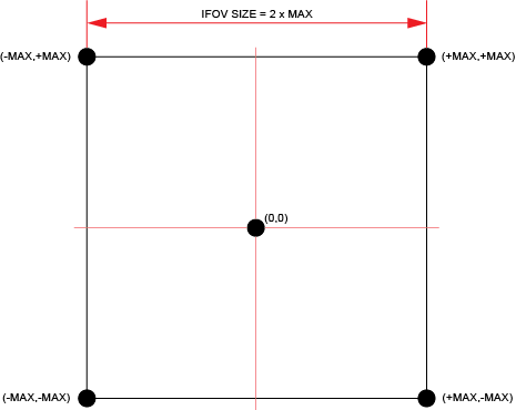
Because the controller tries to operate at the full programmed speed, the controller commands more of the motion to the galvo head. The controller makes sure that the galvo head does not exit the field of view while in IFOV. If you do not want to use the entire field of view of the galvo head, specify a smaller value for this function.
function IfovSetSyncAxes($axes[] as axis)
Configures more axes to command in Infinite Field of View (IFOV).
Arguments
$axes A list of axes to synchronize in Infinite Field of View in addition to those specified in IfovSetAxisPairs().
Use the IfovSetSyncAxes() function to specify more axes to command in IFOV. These axes are added to the axes that you specify for the IfovSetAxisPairs() function. The controller synchronizes all motion functions, I/O functions, and PSO-related functions for all axes in the IFOV configuration. You can specify a maximum of two axes for the IfovSetSyncAxes() function. If you do not want to synchronize more axes, specify an empty array to IfovSetSyncAxes() function.
If you specify axes for this function, the controller synchronizes the following AeroScript functions with Infinite Field of View (IFOV).
- All MoveRapid(), MoveLinear(), MoveCcw(), MoveCw(), and MoveDelay() motion
- AnalogOutputSet() (setting analog outputs)
- DigitalOutputSet() (setting digital outputs)
- PSO functions
- DriveArrayWrite() function
function IfovSetTime($time as integer)
Configures the maximum search time that the controller looks ahead in Infinite Field of View (IFOV).
Arguments
$time The time, in milliseconds, that the controller looks ahead.
Use the IfovSetTime() function to specify the maximum search time, in milliseconds, that the controller looks ahead into your AeroScript program to generate servo motion in Infinite Field of View (IFOV).
Aerotech recommends that you start with a value of 200 milliseconds for $time.
- The value that you use must be an integer that is divisible by 5 milliseconds.
- The value that you use for $time cannot exceed the value that you specify for the IfovMaximumTime parameter.
The value that you set for $time controls the quantity of servo motion that the controller generates. The quantity of servo motion can have an effect on the overall cycle time of your motion program. For more information, refer to the table that follows.
Table: $time Argument Values
|
<SearchTime> |
Motion Effect |
Latency Effect |
|---|---|---|
|
Smaller values |
More servo motion |
Lower initial latency, higher overall cycle time |
|
Larger values |
Less servo motion |
Higher initial latency, lower overall cycle time |
The search time that the controller uses might be less than the value that you specify. This can occur if the programmed laser motion exits the field of view before the servo axes reach the end of the search time. If you specify a larger value for $time, you usually get a lower overall cycle time.
function IfovSetTrackingAcceleration($acceleration![]() The change in velocity as a function of time. as real)
The change in velocity as a function of time. as real)
Configures the maximum acceleration![]() The change in velocity as a function of time. of the servo axes while in Infinite Field of View (IFOV).
The change in velocity as a function of time. of the servo axes while in Infinite Field of View (IFOV).
Arguments
$acceleration![]() The change in velocity as a function of time. The maximum acceleration
The change in velocity as a function of time. The maximum acceleration![]() The change in velocity as a function of time., in user units/second squared, of the servo axes.
The change in velocity as a function of time., in user units/second squared, of the servo axes.
Use the IfovSetTrackingAcceleration() function to specify the maximum acceleration![]() The change in velocity as a function of time. of the servo axes while in Infinite Field of View (IFOV). You must specify an acceleration
The change in velocity as a function of time. of the servo axes while in Infinite Field of View (IFOV). You must specify an acceleration![]() The change in velocity as a function of time. that is greater than zero.
The change in velocity as a function of time. that is greater than zero.
When you enable IFOV, the controller automatically limits the speed and acceleration![]() The change in velocity as a function of time. of the servo axes to keep the galvo head in the field of view.
The change in velocity as a function of time. of the servo axes to keep the galvo head in the field of view.
function IfovSetTrackingSpeed($speed as real)
Configures the maximum speed of the servo axes while in Infinite Field of View (IFOV).
Arguments
$speed The maximum speed, in user units/time base, of the servo axes.
Use the IfovSetTrackingSpeed() function to specify the maximum speed of the servo axes while in Infinite Field of View (IFOV). You must specify a speed that is greater than zero.
When you enable IFOV, the controller automatically limits the speed and acceleration![]() The change in velocity as a function of time. of the servo axes to keep the galvo head in the field of view.
The change in velocity as a function of time. of the servo axes to keep the galvo head in the field of view.
function IfovOn()
Enables Infinite Field of View (IFOV).
IMPORTANT: Before you can enable IFOV, you must set the IfovConfigurations Parameter. Then home the galvo and servo axes and make sure they are in position.
Use IfovOn() to enable IFOV.
While IFOV is enabled, your AeroScript program must command the laser motion to the galvo axes. The controller automatically moves the galvo axes and the servo axes to make the laser motion path that you programmed.
To get the enabled or disabled state of IFOV, retrieve the Ifov Enabled bit of the Axis Status item.
function IfovOff()
Disables Infinite Field of View (IFOV).
Use the IfovOff() function to disable IFOV. If the controller is generating motion while you issue IfovOff(), the controller waits for the motion to complete before it disables IFOV. When IFOV is disabled, the controller clears the position registers so that the galvo axes report the position of the galvo head.


