Joystick Wiring Example
The example that follows shows you how to configure and use a joystick to control the motion of axes X and Y.
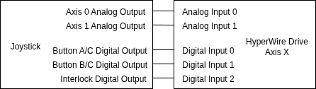
The joystick in this example has the specifications and wiring connections that follow:
- Two joystick axes:
- Each joystick axis produces an analog output voltage in the range of 0 V to +5 V when it is deflected from its central position.
- Deflecting the first joystick axis to the left causes the analog output voltage to decrease towards 0 V. Deflecting the axis to the right causes the analog output voltage to increase towards +5 V.
- Deflecting the second joystick downward causes the analog output voltage to decrease towards 0 V. Deflecting the axis upward causes the analog output voltage to increase towards +5 V.
- Each joystick axis produces an analog output voltage of approximately +2.5 V when it is at its central position.
- The joystick axis analog outputs are connected to Analog Input 0 and Analog Input 1 on the HyperWire drive that corresponds to axis X.
- Each joystick axis produces an analog output voltage in the range of 0 V to +5 V when it is deflected from its central position.
- Joystick buttons A, B, and C:
- The digital outputs of joystick buttons A and B are connected to Digital Input 0 and Digital Input 1 on the HyperWire drive that corresponds to axis X. Joystick button C uses the same digital outputs as buttons A and B.
- A joystick interlock output:
- The joystick interlock digital output is connected to Digital Input 2 on the HyperWire drive that corresponds to axis X.


