Joystick Setup and Operation
Use a joystick to control the axis motion manually. You can command the motion of one to three axes at the same time by deflecting the joystick axes from their central positions. You can configure the joystick buttons to do the functions that follow:
- Cycle through configured axis groups.
- Change the speed of the joystick motion.
- Deactivate the joystick.
For safety, you can also configure an optional joystick interlock input signal to prevent unexpected joystick operation.
Joystick Requirements
A joystick must have the specifications that follow. The Aerotech Multi-axis Joystick has these required specifications.
Axes
- Each joystick axis must have a corresponding analog output signal with a value that changes based on the position of the joystick axis.
- Each analog output signal must produce a voltage within the range of -10 V to +10 V.
- Each analog output signal must be symmetrical.
For Example
A joystick axis might produce voltages in the ranges of 0 V to +5 V, -5 V to +5 V, or -10 V to +10 V.
For Example
A joystick axis that produces a voltage in the range of 0 V and +5 V at its maximum deflection positions must produce a voltage that is approximately +2.5 V at its central position.
Buttons (Optional)
IMPORTANT: Joystick buttons are not required. If you use them, Automation1 supports a maximum of three buttons.
- The controller can support joysticks with a maximum of three buttons (A, B, and C). A joystick can have more buttons, but the joystick feature of the controller does not support them. Table: Applicable Joystick Buttons has a description of each button that you can use.
- If the joystick has a minimum of one button (A), the button must have a corresponding active-high digital output signal. The digital output must be off (0) while the button A is not pressed, and on (1) while the joystick button A is pressed.
- If the joystick has a second button (B), the button must have a corresponding active-high digital output signal. The digital output must be off (0) while the button B is not pressed, and on (1) while the joystick button B is pressed.
- If the joystick has a third button (C), the button must use the same two digital output signals that correspond to joystick buttons A and B. The two digital outputs must be on (1) while button C is pressed. If the joystick does not have a third button (C), you can press buttons A and B at the same time. As a result, the controller will interpret this as you pressing button C.
Table: Applicable Joystick Buttons
| Button Name | Description |
|---|---|
|
A |
Use this button to cycle between groups of motion axes that you configured for control by the joystick axes. |
|
B |
Use this button to toggle between speeds that you configured for the motion of axes that are controlled by the joystick. |
|
C |
Use this button to deactivate the joystick. |
Interlock (Optional)
- For safety, the joystick might have an optional interlock.
- The joystick interlock must have an active-high digital output signal. The digital output must be on (1) while the interlock is active. To disable the interlock, you can change the digital output to off (0).
- If the controller detects that the interlock digital output is off (0) because the digital output was turned off or the interlock digital output signal was disconnected, the controller will stop joystick motion.
Joystick Configuration
Joystick Wiring
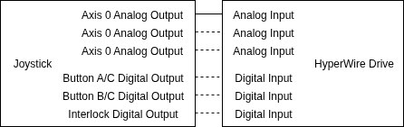
Figure: Basic Joystick Wiring shows a summary of wiring connections to make between a joystick and an Automation1 HyperWire drive. Dashed lines show connections that are optional. For example, a joystick might have fewer than three axes or might not have buttons or an interlock output signal.
To connect a joystick, do the procedure that follows.
- Make sure that you use the correct wiring configuration. Do one of the options that follow:
- For an Aerotech Multi-axis Joystick, use the wiring configuration that is specified in the hardware manual for the HyperWire drive that you are using. To download your manual from www.aerotech.com, go to the Automation1 section of Manuals & Help Files.
- For a custom or third-party joystick, you can use the wiring configuration that is specified in the hardware manual or use a similar configuration.
- Connect the analog outputs that correspond to the joystick axes to analog inputs on one or more HyperWire drives.
- If the joystick has buttons A and B, connect the digital outputs that correspond to joystick buttons A and B to digital inputs. If the joystick has a button C, it must use the same digital outputs that correspond to buttons A and B.
- If the joystick has an interlock digital output signal, connect it to a digital input. Refer to the hardware manual for your HyperWire drives to see possible joystick wiring configurations.
Test the Joystick Wiring
You can examine the values of analog inputs and digital inputs to verify the behavior of the joystick by using any of the status that follow:
- Examine the Diagnostics tab of the Status Utility.
- Examine the Drive I/O tab of the Variables & I/O Module in Automation1 Studio.
- Use the
AnalogInputGet()andDigitalInputGet()AeroScript functions or the status items that follow. See I/O Functions and Data Collection and Controller Status for more information.AnalogInput0AnalogInput1AnalogInput2AnalogInput3DigitalInput
To test each joystick axis, do the procedure that follows:
- Deflect the joystick axis as far as possible in one direction and record the value of the corresponding analog input voltage:
- If the value of the analog input voltage does not change when you deflect the joystick axis, make sure that the joystick wiring is correct.
- If the value of the analog input voltage produces an unexpected value, make sure that the joystick wiring is correct.
For Example
If you expect the value of the analog input voltage to decrease when you move a joystick axis to the left, but the value increases, you might need to fix the wiring of the analog input.
- Deflect the joystick axis as far as possible in the opposite direction. Then record the value of the corresponding analog input voltage.
- Return the joystick axis to its central position. Then record the corresponding analog input voltage.
IMPORTANT: When the joystick is at its central position, the value of the analog input voltage should be approximately the average value of the analog input voltages when the joystick axis is deflected as far as possible in both directions.
To test the joystick buttons, do the procedure that follows:
- If the joystick has a button A, press the joystick button A and make sure that the corresponding digital input bit changes from off (0) to on (1).
- If the joystick has a button B, press the joystick button B and make sure that the corresponding digital input bit changes from off (0) to on (1).
- Test the joystick button C. Do one of the options that follow:
- If the joystick has a button C, press the button and make sure that the digital input bits that correspond to both joystick buttons A and B change from off (0) to on (1).
- If the joystick does not have a button C, press both joystick buttons A and B at the same time and make sure that the digital input bits that correspond to both joystick buttons A and B change from off (0) to on (1).
If the joystick has an interlock digital output signal, make sure that the corresponding digital input bit is on (1) while the joystick is connected. Make sure that the digital input bit is off (0) when the interlock is open or the joystick is disconnected.
Configure the Joystick I/O Inputs
I/O Configuration
Use the parameters JoystickInput0, JoystickInput1, and JoystickInput2 to map the analog output signals produced by joystick axis deflection to analog inputs. To map the analog inputs, do the procedure that follows.
- The joystick must have a minimum of one axis. Use the JoystickInput0 Parameter to specify the analog input that corresponds to the analog output of the first joystick axis.
- If the joystick has a second axis, use the JoystickInput1 Parameter to specify the analog input that corresponds to the analog output of the second joystick axis. If there is no second axis, specify Disabled for the Input Type setting of the parameter.
- If the joystick has a third axis, use the JoystickInput2 Parameter to specify the analog input that corresponds to the analog output of the third joystick axis. If there is no third axis, specify Disabled for the Input Type setting of the parameter.
Use the JoystickAxesSelect Parameter and the JoystickSpeedSelect Parameter to map the buttons of the joystick to digital inputs.
Table: Joystick Button Mapping Parameters
| Button Name | Parameters |
|---|---|
|
A (cycle axis groups) |
|
|
B (toggle joystick speed) |
|
|
C (deactivate joystick) |
To map the digital inputs, do the procedure that follows.
- If the joystick has a button A, use the JoystickAxesSelect Parameter to specify the digital input that corresponds to the digital output of the joystick button A. If the joystick does not have a button A, you must configure the JoystickAxesSelect parameter to use a valid input. The Input Type setting of the parameter must be Drive Digital or Virtual Binary. Select an unused digital input or virtual binary input.
- If the joystick also has a button B, use the JoystickSpeedSelect Parameter to specify the digital input that corresponds to the digital output of the joystick button B. If the joystick does not have a button B, you must configure the JoystickSpeedSelect parameter to use a valid input. The Input Type setting of the parameter must be Drive Digital or Virtual Binary. Select an unused digital input or virtual binary input.
- If the joystick also has a button C, it must use the two digital inputs that correspond to joystick buttons A and B. If the joystick does not have a button C, you can press buttons A and B at the same time. As a result, the controller will interpret this as you pressing button C.
Use the JoystickInterlock Parameter to map the joystick interlock to a digital input. If the joystick does not have an interlock, specify Disabled for the Input Type setting of the parameter.
Voltage Configuration
Calculate the center voltage for a joystick input by using the MinVoltage and MaxVoltage parameters that follow. The MinVoltage and MaxVoltage defaults are set to 0 V and +5 V, which gives a central voltage of 2.5V. Use the Deadband parameters that follow to specify a voltage range in which the joystick is in the center position and no motion occurs. The default Deadband parameters are set to 0.1V, which means that motion will not occur when the joystick voltage is between +2.4 V and +2.6 V. When you first issue the JoystickRun() function, the joystick (including joystick buttons A, B, and C) is not active and will not take control of the axes until all joystick analog inputs are within the deadband range.
Voltage Parameters
- JoystickInput0MinVoltage Parameter
- JoystickInput0MaxVoltage Parameter
- JoystickInput0Deadband Parameter
- JoystickInput1MinVoltage Parameter
- JoystickInput1MaxVoltage Parameter
- JoystickInput1Deadband Parameter
- JoystickInput2MinVoltage Parameter
- JoystickInput2MaxVoltage Parameter
- JoystickInput2Deadband Parameter
Configure the Joystick Feedrates
The controller supplies two speed ranges that you can configure with the JoystickLowSpeed and JoystickHighSpeed parameters. Use these parameters to set the maximum speed of the axis when under joystick control in the specified speed range. The values of these parameters set the maximum speed of the axis in this mode, which occurs at maximum joystick deflection. If you set the values of these parameters to a negative number, it reverses the direction of joystick motion on this axis.
Joystick Operation
Joystick Axis Groups
An axis group represents a single mapping of motion axes to joystick axes. The JoystickInput enum represents an analog input that corresponds to an analog output of a joystick axis and is used with the JoystickAxisGroupAdd() function to configure new axis groups. If you do not add any new axis groups, you will receive a task error when you activate the joystick with the JoystickRun() function.
| enum JoystickInput
Input0 = 0 Input1 = 1 Input2 = 2 end |
Adds an axis group configuration to the joystick configuration.
Arguments
$motionAxes An array of one or more axes to control with the joystick.
$joystickInputs An array of one or more joystick inputs to use to control axes.
You can reset all the axis groups by issuing the JoystickAxisGroupRemoveAll() function.
Removes all axis group configurations from the joystick configuration.
Movement and Control
To gain control of the axes, issue the JoystickRun() function. This will transfer control of motion to the joystick on all axes that you added with the JoystickAxisGroupAdd() function.
Activates the joystick.
Axes that are under joystick control will be shown in yellow on the Axis Dashboard in Automation1 Studio. The Joystick Control bit of AxisStatusItem.AxisStatus also changes to ON.
While the JoystickRun() function is active, the joystick does not control the motion axes until all of the joystick axes have entered the deadband voltage range a minimum of one time. When all of the joystick axes have entered the deadband voltage a minimum of one time, the Joystick Active bit of TaskStatusItem.TaskStatus0 changes to ON for that task.
When you activate the joystick, the joystick initially controls the motion of the first group of axes that you added with the JoystickAxisGroupAdd() function. To change between axis groups, use the joystick button defined by the JoystickAxesSelect Parameter (joystick button A).
Also when you activate the joystick, the joystick initially operates in the low-speed range. To change between the low-speed and high-speed ranges, use the joystick button defined by the JoystickSpeedSelect Parameter (joystick button B). When the joystick is in low-speed mode, the Joystick Low Speed Active bit of TaskStatusItem.TaskStatus0 changes to ON. When the joystick is in high-speed mode, the Joystick Low Speed Active bit of TaskStatusItem.TaskStatus0 changes to OFF.
The joystick button A does not operate if any of the joystick axes are outside of the deadband voltage range. You can use joystick button B and joystick button C when all of the joystick axes are inside or outside of the deadband range.
JoystickRun() is a blocking function. It prevents additional execution of the AeroScript program until one of the following operations occurs:
- You press the joystick button C.
- You open the joystick interlock (if it is configured). See JoystickInterlock Parameter.
- You abort motion on an axis that is under joystick control.
Tip: For an example of how to configure and use a joystick to control the motion of axes, see Joystick Wiring Example.
Test the Joystick I/O Inputs
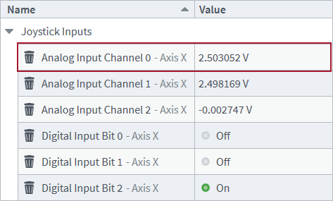
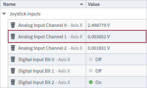
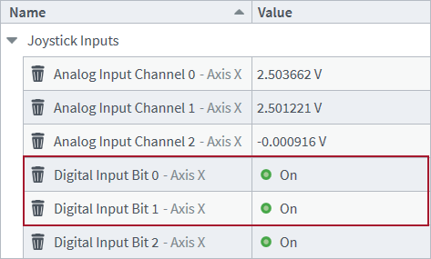
After the joystick is connected, analyze the values of the analog inputs and digital inputs that correspond to the outputs of the joystick. When the joystick axes are at their central positions and none of the joystick buttons are being pressed, the analog inputs should have values that are similar to the values in the figure that follows. The digital inputs should have values that are the same as the values in the figure that follows.
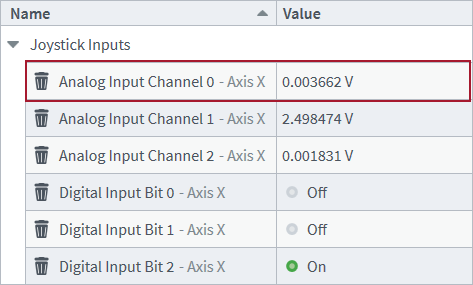
When the first joystick axis is deflected to the furthest possible position to the left, the value of Analog Input 0 should be approximately 0 V.
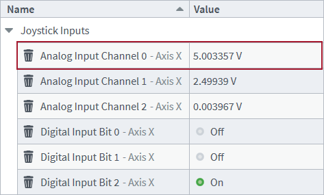
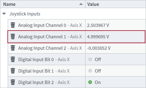
When the first joystick axis is deflected to the furthest possible position to the right, the value of Analog Input 0 should be approximately 5 V.
When the second joystick axis is deflected to the furthest possible position downward, the value of Analog Input 1 should be approximately 0 V.
When the second joystick axis is deflected to the furthest possible position upward, the value of Analog Input 1 should be approximately 5 V.
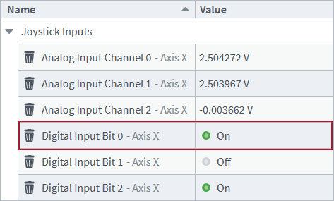
When the joystick button A is pressed, the value of Digital Input bit 0 should be on (1).
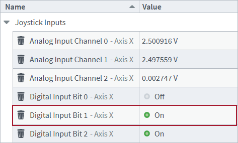
When the joystick button B is pressed, the value of Digital Input bit 1 should be on (1).
When the joystick button C is pressed, the values of Digital Input bit 0 and Digital Input bit 1 should both be on (1).
Configure the Joystick I/O Inputs
I/O Configuration
Edit controller parameters to map the analog and digital outputs of the joystick to analog and digital inputs of the controller. The joystick I/O mapping parameters are in the Tasks > Joystick > Inputs section of the Configure workspace in Automation1 Studio. Click the Pencil icon for each parameter to edit its settings.
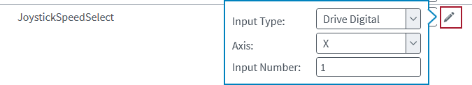
Edit each I/O mapping parameter as follows:
- JoystickAxesSelect
- Input Type: Drive Digital
- Axis: X
- Input Number: 0
- JoystickSpeedSelect
- Input Type: Drive Digital
- Axis: X
- Input Number: 1
- JoystickInterlock
- Input Type: Drive Digital
- Axis: X
- Input Number: 2
- JoystickInput0
- Input Type: Drive Analog
- Axis: X
- Input Number: 0
- JoystickInput1
- Input Type: Drive Analog
- Axis: X
- Input Number: 1
- JoystickInput2
- Input Type: Disabled
- Axis: X
- Input Number: 0
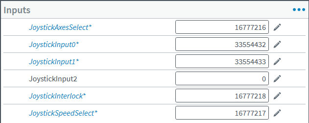
The numeric values of each parameter will appear as follows.
Voltage Configuration
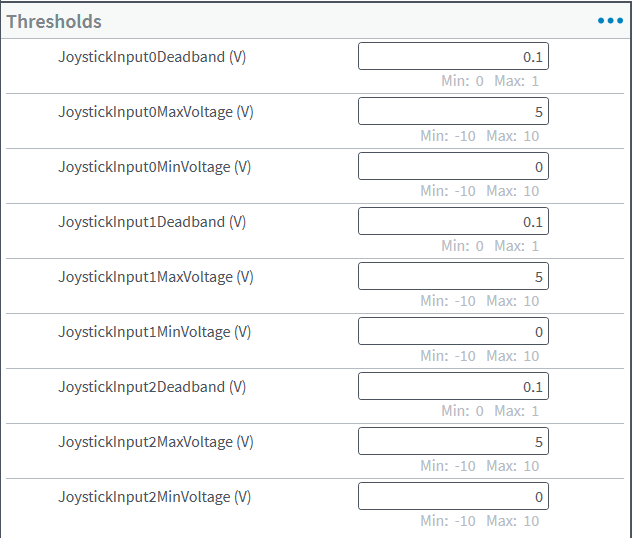
Edit controller parameters to configure voltage settings for each analog input that corresponds to the analog output of a joystick axis. The joystick voltage parameters are in the Tasks > Joystick > Thresholds section of the Configure workspace in Automation1 Studio. For more information about this workspace, see Configure Workspace.
The two joystick axes have a minimum voltage of 0 V and a maximum voltage of +5 V. The default deadband voltage range of 0.1 V is sufficient for the joystick. Because the joystick only has two axes, it is not necessary for you to configure parameters for the third joystick axis. Configure each parameter as follows.
Configure the Joystick Feedrates
Edit controller parameters to configure joystick feedrate settings for each motion axis that will be under the control of the joystick. The joystick feedrate parameters are in the Axes > Motion > Joystick section of the Configure workspace in Automation1 Studio. Configure the JoystickHighSpeed and JoystickLowSpeed parameters for axes X and Y as follows.

Save the changes to these parameters. Then reset the controller.
Test the Joystick Operation
Configure the AeroScript program that follows for your project. Then run it on Task 1 to configure joystick axis groups and enable joystick control of axes X and Y. For information about how to automatically run this program on a task, see Program Automation Module.
// Enable and home the axes that the joystick will control.
Enable([X, Y])
Home([X, Y])

// Remove any existing joystick axis groups.
JoystickAxisGroupRemoveAll()

// Add the initial axis group that controls axes X and Y with both joystick axes.
JoystickAxisGroupAdd([X, Y], [JoystickInput.Input0, JoystickInput.Input1])

// Add an axis group that controls only axis X with the first joystick axis.
JoystickAxisGroupAdd([X], [JoystickInput.Input0])

// Add an axis group that controls only axis Y with the second joystick axis.
JoystickAxisGroupAdd([Y], [JoystickInput.Input1])

// Enable joystick control.
// While joystick control is enabled and joystick axes are within the deadband
// range, you can press the joystick button A to cycle between axis groups.
JoystickRun()
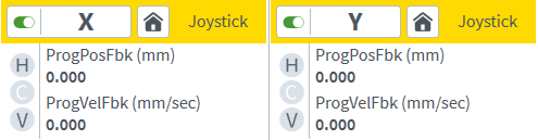
When the JoystickRun() function puts the motion of axes X and Y under the control of the joystick, the Axis Dashboard will show the two axes in yellow. The Joystick Control bit of AxisStatusItem.AxisStatus also changes to ON for the two axes.
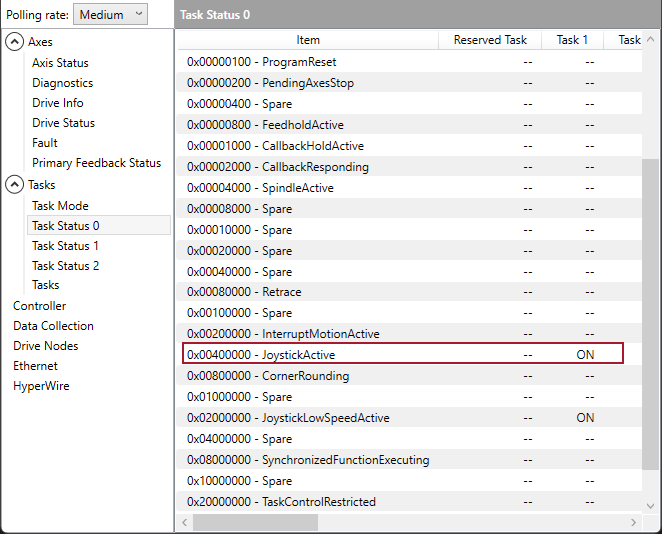
Move the joystick axes to the deadband range. The values of the analog input voltages that correspond to the joystick axes must be in the range of +2.4 V to +2.6 V. When the two joystick axes enter the deadband voltage range, the JoystickActive bit of TaskStatusItem.TaskStatus0 changes to ON for Task 1 and the joystick takes control of the motion of the axes.
By default, the joystick takes control of the first axis group that you configured with the JoystickAxisGroupAdd() function. If you deflect the first joystick axis, the motion axis X will move at a speed that is proportional to the position of the first joystick axis. If you deflect the second joystick axis, the motion axis Y will move at a speed that is proportional to the second joystick axis.
If you press the joystick button A, the joystick takes control of the second axis group that you configured with the JoystickAxisGroupAdd() function. If you press the joystick button A for a second time, the joystick takes control of the third axis group. If you press the joystick button A for a third time, the joystick takes control of the first axis group again.
By default, the joystick is in low-speed mode. When the joystick is in low-speed mode, the Joystick Low Speed Active bit of TaskStatusItem.TaskStatus0 changes to ON and the maximum speed of each motion axis is 25 units per second according to the JoystickLowSpeed axis parameter. If you press the joystick button B, the joystick changes to high-speed mode. When the joystick is in high-speed mode, the Joystick Low Speed Active bit of TaskStatusItem.TaskStatus0 changes to ON and the maximum speed of each motion axis is 100 units per second according to the value of the JoystickHighSpeed parameter.
The joystick is deactivated when one of the following operations occurs:
- You press the joystick button C.
- You open the joystick interlock (if it is configured).
- You abort motion on an axis under joystick control.


