EtherNet/IP Overview
The Automation1 controller supports EtherNet/IP Industrial Ethernet protocol adapters.
EtherNet/IP uses TCP and UDP communication to implement the Common Industrial Protocol (CIP) over an Ethernet connection. CIP is frequently used for communication with Ethernet-based PLCs, I/O modules, and other simple fieldbuses or I/O networks.
EtherNet/IP uses implicit and explicit messaging for communication.
Explicit messaging uses TCP communication to set or get one or more explicit objects. Automation1 does not support vendor-specific explicit objects. Automation1 only supports explicit messaging that is necessary for the EtherNet/IP standard for the objects that follow:
- Identity
- Message router
- TCP/IP
- Ethernet link
- LLDP
- File
Implicit messaging uses UDP communication to send and receive scheduled data between the scanner and adapter. The scanner and adapter exchange data at a fixed Requested Packet Interval (RPI), which can be configured by the EtherNet/IP scanner. Automation1 supports an RPI in the range of 1 millisecond to 1,000 milliseconds. Automation1 supports up to two connections at the same time: the I/O Block 0 and the I/O Block 1 connections. The table that follows shows the information that the EtherNet/IP implicit data model includes.
Table: EtherNet/IP Implicit Data Model
| Connection Name | Implicit Assembly Name | Access |
|---|---|---|
| I/O Block 0 | InputBlock0 | Read-only |
| OutputBlock0 | Read/Write | |
| I/O Block 1 | InputBlock1 | Read-only |
| OutputBlock1 | Read/Write |
Licensing
The Industrial Ethernet (-IE) licensing option of Automation1 supports the EtherNet/IP stacks that are on the controller:
-
-IE1: No EtherNet/IP adapter support
-
-IE2: No EtherNet/IP adapter support
-
-IE3: EtherNet/IP adapter support
Networking
Automation1 supports the EtherNet/IP protocol on PC and drive-based controllers. The supporting hardware is different for the different controller types.
Drive-Based Controllers
Automation1 supports real-time networking capabilities with the EtherNet/IP protocol on drive-based controllers through the onboard Industrial Ethernet network interface. The drive-based controller network interface has two Industrial Ethernet ports labeled A and B. For EtherNet/IP, only port A is available for communication.
Tip: For drive-based controllers, use port A for EtherNet/IP communication.
PC-Based Controllers
PC-based controllers use a dedicated PCIe network interface card (NIC) for Modbus.
IMPORTANT: Modern PC motherboards can have two NICs. Usually, one of the NICs can be used by INtime to support Industrial Ethernet communication.
Supported families of network cards:
-
Broadcom Gigabit (bge1g.rsl)
-
Intel 10/100Mbps (ie100m.rsl)
-
Intel Gigabit (ie1g.rsl)
-
RealTek 10/100 Mbps (rtl100m.rsl)
-
RealTek Gigabit (rtl1g.rsl)
See the Compatible Network Interface Cards section for individual device information.
Installation
Automation1 NICs for Modbus are passed to INtime in the same manner as the HyperWire card. After installing a standalone PCIe NIC or just utilizing a secondary, dedicated motherboard NIC, do the procedure that follows to pass the card to INtime control.
-
Open INtime Device Manager. (Start > All Programs > INtime > INtime Configuration. Then double-click INtime Device Manager).
-
In the Windows devices tree, find your network adapter. Right-click your adapter and select Pass to INtime using MSI.
-
Click File and then select Save the Configuration. The card will now be listed under the INtime devices tree.
-
Close INtime Device Manager.
IP Configuration
Use Automation1 Studio to configure the applicable device driver for your network interface and to configure the IP networking information.
-
In Automation1 Studio, go to the Develop workspace. Then go to the Variables & I/O module.
-
At the top of the module, select the Industrial Ethernet tab. For more information about this tab, see the Industrial Ethernet Tab section of the Variables & I/O module in the Develop workspace.
-
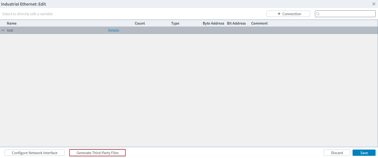
Click the Edit button. The Industrial Ethernet: Edit dialog comes into view.
-
On the dialog, click the Configure Network Interface button in the bottom left corner.
-
On the Configure Network Interface screen, select the applicable driver for your NIC.
-
Enter the IP Address, Subnet Mask, and Gateway values.
-
To use DHCP, click the Automatically assign IP address using DHCP server toggle to the "on" position. To clear the NIC configuration, click the Clear Configuration button in the bottom left corner.
-
When you are done entering your information, click the Save button on the Configure Network Interface screen and again on the Industrial Ethernet: Edit screen.


Create an EtherNet/IP Adapter Connection
You must create a connection to enable the EtherNet/IP adapter on the controller. To manage the current connections, click the Edit button on the Industrial Ethernet tab. For more information about this tab, see the Industrial Ethernet Tab section of the Variables & I/O module in the Develop workspace.
- On the Industrial Ethernet tab, click the Edit button. The Industrial Ethernet: Edit dialog comes into view.
- Click the + Connection button.
- Enter your information into the fields on the Connection Details screen.
- In the Name field, add the name of the EtherNet/IP adapter. The name field is required but is only informational and is used to identify the different EtherNet/IP adapter connections in Automation1.
- Click the Add button to save the connection information.
Data Access
After you create a connection, you can add variable mappings to it. Automation1 uses Industrial Ethernet mappings to expose the implicit messaging assemblies of the EtherNet/IP adapter. These Industrial Ethernet mappings connect the memory regions of the EtherNet/IP adapter data to arbitrary controller data types. The table that follows shows the access level of the registers.
Table: Register Access Level
| EtherNet/IP Assembly | Automation1 Register | Access |
|---|---|---|
| InputBlock0 | Input Block 0 | Read-only |
| OutputBlock0 | Output Block 0 | Read/Write |
| InputBlock1 | Input Block 1 | Read-only |
| OutputBlock1 | Output Block 1 | Read/Write |
You can configure the fields that follow for each Industrial Ethernet register mapping:
-
Name: Specifies the name of the variable. The name is automatically converted into an AeroScript variable by the controller. You can then use it in programs or libraries.
-
Count: Specifies how many consecutive sequences there are of this variable.
-
Type: Configures the EtherNet/IP data as the specified data type. See the Supported Data Types table that follows for the data types that are supported.
-
Byte Address: Configures the byte offset of the register.
-
Bit Address: Configures the bit offset of the register.
-
The final address is the sum of byteAddress * 8 + bitAddress.
-
Non-bit data types must be 8-bit byte aligned.
-
-
Comment: You can add information about the mapping.
| Data Type | Description |
|---|---|
| Bit | 1-bit Boolean value |
| UInt8 | 8-bit unsigned integer |
| UInt16 | 16-bit unsigned integer |
| UInt32 | 32-bit unsigned integer |
| Int8 | 8-bit signed integer |
| Int16 | 16-bit signed integer |
| Int32 | 32-bit signed integer |
| Float32 | 32-bit single-precision floating-point value |
| Float64 | 64-bit double-precision floating-point value |
-
On the Industrial Ethernet tab in the Variables & I/O module, click the Edit button.
-
On the Industrial Ethernet: Edit dialog that comes into view, you can see the connections that you created. Click the arrow next to the connection that you want to add mappings to.
-
In the rows that now show under the connection, click the + button to configure the fields described in the list above.
-
Click the Save button when you are done.
AeroScript
After you configure the Industrial Ethernet mappings, the controller automatically converts the information into AeroScript properties. The code sample that follows shows the properties that would be generated from an example mapping.
Table: AeroScript Properties for Industrial Ethernet Mappings
| Register | Name | Count | Type | Byte Address | Bit Address |
|---|---|---|---|---|---|
| Input Block0 | inInt | 1 | Uint32 | 0 | 0 |
| Output Block 0 | outReals | 4 | Float64 | 8 | 0 |
Industrial Ethernet mappings converted into AeroScript
library property $inInt as integer
library property $outReals[$index as integer] as real
Export AeroScript Mappings to Third-Party Files
You can export EtherNet/IP Adapter mappings to use with third-party EtherNet/IP Scanners that are using Automation1 Studio.
-
Go to the Industrial Ethernet: Edit screen by clicking the Edit button on the Industrial Ethernet tab.
-
Make sure that the Generate Third-Party Files button is available. This button only shows if you have an EtherNet/IP Adapter configured.
-
Click the Generate Third-Party Files button to create a set of third-party files based on the configured mappings. One file is generated for each EtherNet/IP assembly that has mappings.
-
Select the third-party file type and destination directory.
-
Import the third-party files into your EtherNet/IP scanner software.
-
In the Controller Organizer, right click on the User Defined heading under Assets > Data types.
-
Select Import Data Type.
-
Select the UDT file that you want to import, and click OK to start.
-
Do this again for the other UDT files that you created.
IMPORTANT: If the configured AeroScript mappings violate the alignment rules for the selected third-party file type, one or more warnings will show. A third party file can only be created if there are no alignment warnings.
For example, if Studio 5000 was your scanner software, you would use the steps that follow to import the third-party files that you generated.
EtherNet/IP Status Items / Data Collection
Automation1 supplies many EtherNet/IP status items that you can use directly in a program or through Data Collection. All of the EtherNet/IP status items are in the System category. You can get EtherNet/IP status items with the StatusGetSystemItem() function. You can add the EtherNet/IP status items to Data Collection with the DataCollectionAddSystemSignal() function.
Tip: If Automation1 encounters
To get status information for the EtherNet/IP adapter configuration, use the status items that follow:
-
EtherNetIp Adapter Enabled
-
EtherNetIp Adapter Connected
-
EtherNetIp Adapter Error
To get the number of bytes in each of the input and output assemblies configured on the EtherNet/IP scanner, use the status items that follow:
-
EtherNetIp Adapter Input Block 0 Size
-
EtherNetIp Adapter Input Block 1 Size
-
EtherNetIp Adapter Output Block 0 Size
-
EtherNetIp Adapter Output Block 1 Size
To get access to the data that is sent over the EtherNet/IP connection, use the status items that follow:
-
EtherNetIp Adapter Input Block 0
-
EtherNetIp Adapter Input Block 1
-
EtherNetIp Adapter Output Block 0
-
EtherNetIp Adapter Output Block 1
The Input Block and the Output Block status items must have one more data field to specify the connection index, data type, byte offset, and bit offset. See the list that follows:
-
$Index: The index of the connection defined in Automation1. The first created connection is index 0. To see the currently defined connections, go to the Variables & I/O module in the Develop workspace and open the Industrial Ethernet tab.
-
$DataType: The type of the data.
-
$BitOffset: The bit offset of the data item as defined in the EtherNet/IP mapping.
-
$ByteOffset: The byte offset of the data item as defined in the EtherNet/IP mapping.
To find the correct additional data value, use the computeEtherNetIpAdditionalData() function. If you want to use this function, you must add the code to your AeroScript program. See the example that follows.
Program Example: Finding the correct additional data value
function computeEtherNetIpAdditionalData($Index as integer, $DataType as EtherNetIpRegisterDataType, $BitOffset as integer, $ByteOffset as integer) as integer
	var $additionalData as integer
	$additionalData = ($Index << 28) & 0xF0000000 | ($DataType << 23) & 0x0F800000 | ($BitOffset << 20) & 0x00700000 | ($ByteOffset & 0x000FFFFF)
	return $additionalData
end

program
	$iglobal[0] = computeEtherNetIpAdditionalData(0, EtherNetIpRegisterDataType.Float64, 0, 256)
end
Troubleshooting
If you cannot make a connection between Automation1 and your EtherNet/IP scanner, try the troubleshooting steps that follow.
-
If you are using a PC-based controller, make sure that you selected the correct driver for your network card as listed in the Compatible Network Interface Cards section.
-
If you are using a PC-based controller, make sure that your network card is passed to INtime in the INtime Device Manager. See the Installation section on this page.
-
Use the Status Utility to make sure that the network information you entered is correct. The Ethernet tab shows the Industrial Ethernet Network information.
Table: Industrial Ethernet Network Information
| Industrial Ethernet Network Item | Description |
|---|---|
| DHCP | Shows if the Industrial Ethernet Network is configured to use DHCP |
| IP Address | The IP address of the Industrial Ethernet Network |
| Subnet Mask | The Subnet Mask of the Industrial Ethernet Network |
| Default Gateway | The Default Gateway of the Industrial Ethernet Network |
| MAC Address | The MAC Address of the Industrial Ethernet Network adapter |
| MTU Size | The MTU size of the Industrial Ethernet Network |
| Estimated Link Speed (Mbps) | The estimated speed of the link layer of the Industrial Ethernet Network in Mbps |
-
Use the Status Utility to make sure that an EtherNet/IP adapter is configured and running. The Ethernet tab shows the EtherNet/IP information.
Table: Industrial Ethernet Network Information
| EtherNet/IP Item | Description |
|---|---|
| EtherNet/IP Adapter Enabled | Shows if the Industrial Ethernet mappings contain an EtherNet/IP adapter configuration |
| EtherNet/IP Adapter Connected | Shows if the EtherNet/IP adapter has an active connection with an EtherNet/IP scanner |
| EtherNet/IP Adapter Connection Error | Shows the active connection error on the EtherNet/IP adapter, if there is one |
| Input Block 0 Size | Number of bytes configured for data coming to Automation1 from the scanner using the InputBlock0 assembly |
| Input Block 1 Size | Number of bytes configured for data coming to Automation1 from the scanner using the InputBlock1 assembly |
| Output Block 0 Size | Number of bytes configured for data going from Automation1 to the scanner using the OutputBlock0 assembly |
| Output Block 1 Size | Number of bytes configured for data going from Automation1 to the scanner using the OutputBlock1 assembly |

-
If you are using a PC controller, try to ping your network card and the EtherNet/IP device you are trying to connect with through the INtime ping utility. Use the INtime RT Application Loader to run the
ping.rtabinary in the network7 folder.-
You can ping the address of your network card to make sure INtime can communicate with the card.
-
You can ping the address of the EtherNet/IP scanner you are trying to connect with to make sure that the Automation1 PC can reach the destination IP address.
-
- If you cannot ping your device, make sure that there is not a firewall preventing traffic between the two devices. If you are using a firewall, you will have to add an exception for the EtherNet/IP network traffic.
Compatible Network Interface Cards
The NIC devices that follow are supported by INtime to use with EtherNet/IP on the PC-based Automation1 controller. Select the drop-down based on the version of INtime installed on your PC.
Select INtime 7.0.23244.1 if you originally installed Automation1 2.7 or newer on your PC.
Select INtime 6.4.19245.2 if you originally installed Automation1 2.6 or older on your PC.
| Vendor ID | Device ID | Description |
|---|---|---|
| 106b | 1645 | APPLE_DEVICE_BCM5701 |
| 10b7 | 0003 | TC_DEVICEID_3C996 |
| 1148 | 4400 | SK_DEVICEID_ALTIMA |
| 12ae | 0003 | ALTEON_DEVICEID_BCM5700 |
| 12ae | 0004 | ALTEON_DEVICEID_BCM5701 |
| 14e4 | 1600 | BCOM_DEVICEID_BCM5752 |
| 14e4 | 1601 | BCOM_DEVICEID_BCM5752M |
| 14e4 | 1644 | BCOM_DEVICEID_BCM5700 |
| 14e4 | 1645 | BCOM_DEVICEID_BCM5701 |
| 14e4 | 1646 | BCOM_DEVICEID_BCM5702 |
| 14e4 | 1647 | BCOM_DEVICEID_BCM5703 |
| 14e4 | 1648 | BCOM_DEVICEID_BCM5704C |
| 14e4 | 1649 | BCOM_DEVICEID_BCM5704S_ALT |
| 14e4 | 1653 | BCOM_DEVICEID_BCM5705 |
| 14e4 | 1654 | BCOM_DEVICEID_BCM5705K |
| 14e4 | 1658 | BCOM_DEVICEID_BCM5720 |
| 14e4 | 1659 | BCOM_DEVICEID_BCM5721 |
| 14e4 | 165a | BCOM_DEVICEID_BCM5722 |
| 14e4 | 165b | BCOM_DEVICEID_BCM5723 |
| 14e4 | 165d | BCOM_DEVICEID_BCM5705M |
| 14e4 | 165e | BCOM_DEVICEID_BCM5705M_ALT |
| 14e4 | 1668 | BCOM_DEVICEID_BCM5714C |
| 14e4 | 1669 | BCOM_DEVICEID_BCM5714S |
| 14e4 | 166a | BCOM_DEVICEID_BCM5780 |
| 14e4 | 166b | BCOM_DEVICEID_BCM5780S |
| 14e4 | 166e | BCOM_DEVICEID_BCM5705F |
| 14e4 | 1672 | BCOM_DEVICEID_BCM5754M |
| 14e4 | 1673 | BCOM_DEVICEID_BCM5755M |
| 14e4 | 1674 | BCOM_DEVICEID_BCM5756 |
| 14e4 | 1676 | BCOM_DEVICEID_BCM5750 |
| 14e4 | 1677 | BCOM_DEVICEID_BCM5751 |
| 14e4 | 1678 | BCOM_DEVICEID_BCM5715 |
| 14e4 | 1679 | BCOM_DEVICEID_BCM5715S |
| 14e4 | 167a | BCOM_DEVICEID_BCM5754 |
| 14e4 | 167b | BCOM_DEVICEID_BCM5755 |
| 14e4 | 167c | BCOM_DEVICEID_BCM5750M |
| 14e4 | 167d | BCOM_DEVICEID_BCM5751M |
| 14e4 | 167e | BCOM_DEVICEID_BCM5751F |
| 14e4 | 1680 | BCOM_DEVICEID_BCM5761E |
| 14e4 | 1681 | BCOM_DEVICEID_BCM5761 |
| 14e4 | 1684 | BCOM_DEVICEID_BCM5764 |
| 14e4 | 1688 | BCOM_DEVICEID_BCM5761S |
| 14e4 | 1689 | BCOM_DEVICEID_BCM5761SE |
| 14e4 | 168c | BCOM_DEVICEID_BCM57720 |
| 14e4 | 1690 | BCOM_DEVICEID_BCM57760 |
| 14e4 | 1692 | BCOM_DEVICEID_BCM57780 |
| 14e4 | 1693 | BCOM_DEVICEID_BCM5787M |
| 14e4 | 1694 | BCOM_DEVICEID_BCM57790 |
| 14e4 | 1696 | BCOM_DEVICEID_BCM5782 |
| 14e4 | 1698 | BCOM_DEVICEID_BCM5784 |
| 14e4 | 1699 | BCOM_DEVICEID_BCM5785 |
| 14e4 | 169a | BCOM_DEVICEID_BCM5786 |
| 14e4 | 169b | BCOM_DEVICEID_BCM5787 |
| 14e4 | 169c | BCOM_DEVICEID_BCM5788 |
| 14e4 | 169d | BCOM_DEVICEID_BCM5789 |
| 14e4 | 16a6 | BCOM_DEVICEID_BCM5702X |
| 14e4 | 16a7 | BCOM_DEVICEID_BCM5703X |
| 14e4 | 16a8 | BCOM_DEVICEID_BCM5704S |
| 14e4 | 16c6 | BCOM_DEVICEID_BCM5702_ALT |
| 14e4 | 16c7 | BCOM_DEVICEID_BCM5703_ALT |
| 14e4 | 16dd | BCOM_DEVICEID_BCM5781 |
| 14e4 | 16f7 | BCOM_DEVICEID_BCM5753 |
| 14e4 | 16fd | BCOM_DEVICEID_BCM5753M |
| 14e4 | 16fe | BCOM_DEVICEID_BCM5753F |
| 14e4 | 16ff | BCOM_DEVICEID_BCM5903M |
| 14e4 | 170d | BCOM_DEVICEID_BCM5901 |
| 14e4 | 170e | BCOM_DEVICEID_BCM5901A2 |
| 14e4 | 1712 | BCOM_DEVICEID_BCM5906 |
| 14e4 | 1713 | BCOM_DEVICEID_BCM5906M |
| 173b | 03e8 | ALTIMA_DEVICE_AC1000 |
| 173b | 03e9 | ALTIMA_DEVICE_AC1002 |
| 173b | 03ea | ALTIMA_DEVICE_AC9100 |
| Vendor ID | Device ID | Description |
|---|---|---|
| 8086 | 10b6 | 82598 |
| 8086 | 10c6 | 82598AF_DUAL_PORT |
| 8086 | 10c7 | 82598AF_SINGLE_PORT |
| 8086 | 10c8 | 82598AT |
| 8086 | 10db | 82598EB_SFP_LOM |
| 8086 | 10dd | 82598EB_CX4 |
| 8086 | 10e1 | 82598_SR_DUAL_PORT_EM |
| 8086 | 10ec | 82598_CX4_DUAL_PORT |
| 8086 | 10f1 | 82598_DA_DUAL_PORT |
| 8086 | 10f4 | 82598EB_XF_LR |
| 8086 | 10f7 | 82599_KX4 |
| 8086 | 10f8 | 82599_COMBO_BACKPLANE |
| 8086 | 10f9 | 82599_CX4 |
| 8086 | 10fb | 82599_SFP |
| 8086 | 10fc | 82599_XAUI_LOM |
| 8086 | 150b | 82598AT2 |
| 8086 | 1514 | 82599_KX4_MEZZ |
| 8086 | 151c | 82599_T3_LOM |
| 8086 | 1528 | X540T |
| 8086 | 1529 | 82599_SFP_FCOE |
| 8086 | 152a | 82599_BACKPLANE_FCOE |
| 8086 | 154a | 82599_SFP_SF_QP |
| 8086 | 154d | 82599_SFP_SF2 |
| 8086 | 1557 | 82599EN_SFP |
| 8086 | 1558 | 82599_QSFP_SF_QP |
| 8086 | 155c | X540_BYPASS |
| 8086 | 155d | 82599_BYPASS |
| 8086 | 1560 | X540T1 |
| 8086 | 1563 | X550T |
| 8086 | 15aa | X550EM_X_KX4 |
| 8086 | 15ab | X550EM_X_KR |
| 8086 | 15ac | X550EM_X_SFP |
| 8086 | 15ad | X550EM_X_10G_T |
| 8086 | 15ae | X550EM_X_1G_T |
| 8086 | 15c2 | X550EM_A_KR |
| 8086 | 15c3 | X550EM_A_KR_L |
| 8086 | 15c4 | X550EM_A_SFP_N |
| 8086 | 15c6 | X550EM_A_SGMII |
| 8086 | 15c7 | X550EM_A_SGMII_L |
| 8086 | 15c8 | X550EM_A_10G_T |
| 8086 | 15ce | X550EM_A_SFP |
| 8086 | 15d1 | X550T1 |
| 8086 | 15e4 | X550EM_A_1G_T |
| 8086 | 15e5 | X550EM_A_1G_T_L |
| Vendor ID | Device ID | Description |
|---|---|---|
| 8086 | 0438 | DH89XXCC_SGMII |
| 8086 | 043a | DH89XXCC_SERDES |
| 8086 | 043c | DH89XXCC_BACKPLANE |
| 8086 | 0440 | DH89XXCC_SFP |
| 8086 | 0d4c | PCH_CMP_I219_LM11. |
| 8086 | 0d4d | PCH_CMP_I219_V11. |
| 8086 | 0d4e | PCH_CMP_I219_LM10. |
| 8086 | 0d4f | PCH_CMP_I219_V10. |
| 8086 | 0d53 | PCH_CMP_I219_LM12. |
| 8086 | 0d55 | PCH_CMP_I219_V12. |
| 8086 | 1000 | 82542 |
| 8086 | 1001 | 82543GC_FIBER |
| 8086 | 1004 | 82543GC_COPPER |
| 8086 | 1008 | 82544EI_COPPER |
| 8086 | 1009 | 82544EI_FIBER |
| 8086 | 100c | 82544GC_COPPER |
| 8086 | 100d | 82544GC_LOM |
| 8086 | 100e | 82540EM |
| 8086 | 100f | 82545EM_COPPER |
| 8086 | 1010 | 82546EB_COPPER |
| 8086 | 1011 | 82545EM_FIBER |
| 8086 | 1012 | 82546EB_FIBER |
| 8086 | 1013 | 82541EI |
| 8086 | 1014 | 82541ER_LOM |
| 8086 | 1015 | 82540EM_LOM |
| 8086 | 1016 | 82540EP_LOM |
| 8086 | 1017 | 82540EP |
| 8086 | 1018 | 82541EI_MOBILE |
| 8086 | 1019 | 82547EI |
| 8086 | 101a | 82547EI_MOBILE |
| 8086 | 101d | 82546EB_QUAD_COPPER |
| 8086 | 101e | 82540EP_LP |
| 8086 | 1026 | 82545GM_COPPER |
| 8086 | 1027 | 82545GM_FIBER |
| 8086 | 1028 | 82545GM_SERDES |
| 8086 | 1049 | ICH8_IGP_M_AMT. |
| 8086 | 104a | ICH8_IGP_AMT. |
| 8086 | 104b | ICH8_IGP_C. |
| 8086 | 104c | ICH8_IFE. |
| 8086 | 104d | ICH8_IGP_M. |
| 8086 | 105e | 82571EB_COPPER. |
| 8086 | 105f | 82571EB_FIBER. |
| 8086 | 1060 | 82571EB_SERDES. |
| 8086 | 1075 | 82547GI |
| 8086 | 1076 | 82541GI |
| 8086 | 1077 | 82541GI_MOBILE |
| 8086 | 1078 | 82541ER |
| 8086 | 1079 | 82546GB_COPPER |
| 8086 | 107a | 82546GB_FIBER |
| 8086 | 107b | 82546GB_SERDES |
| 8086 | 107c | 82541GI_LF |
| 8086 | 107d | 82572EI_COPPER. |
| 8086 | 107e | 82572EI_FIBER. |
| 8086 | 107f | 82572EI_SERDES. |
| 8086 | 108a | 82546GB_PCIE |
| 8086 | 108b | 82573E. |
| 8086 | 108c | 82573E_IAMT. |
| 8086 | 1096 | 80003ES2LAN_COPPER_DPT. |
| 8086 | 1098 | 80003ES2LAN_SERDES_DPT. |
| 8086 | 1099 | 82546GB_QUAD_COPPER |
| 8086 | 109a | 82573L. |
| 8086 | 10a4 | 82571EB_QUAD_COPPER. |
| 8086 | 10a5 | 82571EB_QUAD_FIBER. |
| 8086 | 10a7 | 82575EB_COPPER |
| 8086 | 10a9 | 82575EB_FIBER_SERDES |
| 8086 | 10b5 | 82546GB_QUAD_COPPER_KSP3 |
| 8086 | 10b9 | 82572EI. |
| 8086 | 10ba | 80003ES2LAN_COPPER_SPT. |
| 8086 | 10bb | 80003ES2LAN_SERDES_SPT. |
| 8086 | 10bc | 82571EB_QUAD_COPPER_LP. |
| 8086 | 10bd | ICH9_IGP_AMT. |
| 8086 | 10bf | ICH9_IGP_M. |
| 8086 | 10c0 | ICH9_IFE. |
| 8086 | 10c2 | ICH9_IFE_G. |
| 8086 | 10c3 | ICH9_IFE_GT. |
| 8086 | 10c4 | ICH8_IFE_GT. |
| 8086 | 10c5 | ICH8_IFE_G. |
| 8086 | 10c9 | 82576 |
| 8086 | 10ca | 82576_VF |
| 8086 | 10cb | ICH9_IGP_M_V. |
| 8086 | 10cc | ICH10_R_BM_LM. |
| 8086 | 10cd | ICH10_R_BM_LF. |
| 8086 | 10ce | ICH10_R_BM_V. |
| 8086 | 10d3 | 82574L. |
| 8086 | 10d5 | 82571PT_QUAD_COPPER. |
| 8086 | 10d6 | 82575GB_QUAD_COPPER |
| 8086 | 10d9 | 82571EB_SERDES_DUAL. |
| 8086 | 10da | 82571EB_SERDES_QUAD. |
| 8086 | 10de | ICH10_D_BM_LM. |
| 8086 | 10df | ICH10_D_BM_LF. |
| 8086 | 10e5 | ICH9_BM. |
| 8086 | 10e6 | 82576_FIBER |
| 8086 | 10e7 | 82576_SERDES |
| 8086 | 10e8 | 82576_QUAD_COPPER |
| 8086 | 10ea | PCH_M_HV_LM. |
| 8086 | 10eb | PCH_M_HV_LC. |
| 8086 | 10ef | PCH_D_HV_DM. |
| 8086 | 10f0 | PCH_D_HV_DC. |
| 8086 | 10f5 | ICH9_IGP_M_AMT. |
| 8086 | 10f6 | 82574LA. |
| 8086 | 1501 | ICH8_82567V_3. |
| 8086 | 1502 | PCH2_LV_LM. |
| 8086 | 1503 | PCH2_LV_V. |
| 8086 | 150a | 82576_NS |
| 8086 | 150c | 82583V. |
| 8086 | 150d | 82576_SERDES_QUAD |
| 8086 | 150e | 82580_COPPER |
| 8086 | 150f | 82580_FIBER |
| 8086 | 1510 | 82580_SERDES |
| 8086 | 1511 | 82580_SGMII |
| 8086 | 1516 | 82580_COPPER_DUAL |
| 8086 | 1518 | 82576_NS_SERDES |
| 8086 | 1520 | I350_VF |
| 8086 | 1521 | I350_COPPER |
| 8086 | 1522 | I350_FIBER |
| 8086 | 1523 | I350_SERDES |
| 8086 | 1524 | I350_SGMII |
| 8086 | 1525 | ICH10_D_BM_V. |
| 8086 | 1526 | 82576_QUAD_COPPER_ET2 |
| 8086 | 1527 | 82580_QUAD_FIBER |
| 8086 | 1533 | I210_COPPER |
| 8086 | 1534 | I210_COPPER_OEM1 |
| 8086 | 1535 | I210_COPPER_IT |
| 8086 | 1536 | I210_FIBER |
| 8086 | 1537 | I210_SERDES |
| 8086 | 1538 | I210_SGMII |
| 8086 | 1539 | I211_COPPER |
| 8086 | 153a | PCH_LPT_I217_LM. |
| 8086 | 153b | PCH_LPT_I217_V. |
| 8086 | 1559 | PCH_LPTLP_I218_V. |
| 8086 | 155a | PCH_LPTLP_I218_LM. |
| 8086 | 156f | PCH_SPT_I219_LM. |
| 8086 | 1570 | PCH_SPT_I219_V. |
| 8086 | 157b | I210_COPPER_FLASHLESS |
| 8086 | 157c | I210_SERDES_FLASHLESS |
| 8086 | 15a0 | PCH_I218_LM2. |
| 8086 | 15a1 | PCH_I218_V2. |
| 8086 | 15a2 | PCH_I218_LM3. |
| 8086 | 15a3 | PCH_I218_V3. |
| 8086 | 15b7 | PCH_SPT_I219_LM2. |
| 8086 | 15b8 | PCH_SPT_I219_V2. |
| 8086 | 15b9 | PCH_LBG_I219_LM3. |
| 8086 | 15bb | PCH_CNP_I219_LM7. |
| 8086 | 15bc | PCH_CNP_I219_V7. |
| 8086 | 15bd | PCH_CNP_I219_LM6. |
| 8086 | 15be | PCH_CNP_I219_V6. |
| 8086 | 15d6 | PCH_SPT_I219_V5. |
| 8086 | 15d7 | PCH_SPT_I219_LM4. |
| 8086 | 15d8 | PCH_SPT_I219_V4. |
| 8086 | 15df | PCH_ICP_I219_LM8. |
| 8086 | 15e0 | PCH_ICP_I219_V8. |
| 8086 | 15e1 | PCH_ICP_I219_LM9. |
| 8086 | 15e2 | PCH_ICP_I219_V9. |
| 8086 | 15e3 | PCH_SPT_I219_LM5. |
| 8086 | 15f4 | PCH_TGP_I219_LM15. |
| 8086 | 15f5 | PCH_TGP_I219_V15. |
| 8086 | 15f9 | PCH_TGP_I219_LM14. |
| 8086 | 15fa | PCH_TGP_I219_V14. |
| 8086 | 15fb | PCH_TGP_I219_LM13. |
| 8086 | 15fc | PCH_TGP_I219_V13. |
| 8086 | 1a1c | PCH_ADL_I219_LM17. |
| 8086 | 1a1d | PCH_ADL_I219_V17. |
| 8086 | 1a1e | PCH_ADL_I219_LM16. |
| 8086 | 1a1f | PCH_ADL_I219_V16. |
| 8086 | 1f40 | I354_BACKPLANE_1GBPS |
| 8086 | 1f41 | I354_SGMII |
| 8086 | 1f45 | I354_BACKPLANE_2_5GBPS |
| 8086 | 294c | ICH9_IGP_C. |
| 8086 | 550a | PCH_MTP_I219_LM18. |
| 8086 | 550b | PCH_MTP_I219_V18. |
| 8086 | 550c | PCH_MTP_I219_LM19. |
| 8086 | 550d | PCH_MTP_I219_V19. |
| Vendor ID | Device ID | Description |
|---|---|---|
| 8086 | 101f | 5G_BASE_T_BC |
| 8086 | 104e | 10G_SFP |
| 8086 | 104f | 10G_B |
| 8086 | 1572 | SFP_XL710 |
| 8086 | 1580 | KX_B |
| 8086 | 1581 | KX_C |
| 8086 | 1583 | QSFP_A |
| 8086 | 1584 | QSFP_B |
| 8086 | 1585 | QSFP_C |
| 8086 | 1586 | 10G_BASE_T |
| 8086 | 1589 | 10G_BASE_T4 |
| 8086 | 158a | 25G_B |
| 8086 | 158b | 25G_SFP28 |
| 8086 | 15ff | 10G_BASE_T_BC |
| 8086 | 37ce | KX_X722 |
| 8086 | 37cf | QSFP_X722 |
| 8086 | 37d0 | SFP_X722 |
| 8086 | 37d1 | 1G_BASE_T_X722 |
| 8086 | 37d2 | 10G_BASE_T_X722 |
| 8086 | 37d3 | SFP_I_X722 |
Aerotech does not support using this network driver in Automation1.
| Vendor ID | Device ID | Description |
|---|---|---|
| 10ec | 8125 | Realtek PCIe 2.5GbE Family Controller |
| 10ec | 8136 | Realtek PCIe FE Family Controller |
| 10ec | 8161 | Realtek PCIe GbE Family Controller |
| 10ec | 8167 | Realtek PCI GbE Family Controller |
| 10ec | 8168 | Realtek PCIe GbE Family Controller |
| 10ec | 8169 | Realtek PCI GbE Family Controller |
| 1186 | 4300 | Realtek PCI GbE Family Controller |
Aerotech does not support using this network driver in Automation1.
Aerotech does not support using this network driver in Automation1.
Aerotech does not support using this network driver in Automation1.
| Vendor ID | Device ID | Description |
|---|---|---|
| 106B | 1645 | APPLE_DEVICE_BCM5701 |
| 10B7 | 0003 | TC_DEVICEID_3C996 |
| 1148 | 4400 | SK_DEVICEID_ALTIMA |
| 12AE | 0003 | ALTEON_DEVICEID_BCM5700 |
| 12AE | 0004 | ALTEON_DEVICEID_BCM5701 |
| 14E4 | 1600 | BCOM_DEVICEID_BCM5752 |
| 14E4 | 1601 | BCOM_DEVICEID_BCM5752M |
| 14E4 | 1644 | BCOM_DEVICEID_BCM5700 |
| 14E4 | 1645 | BCOM_DEVICEID_BCM5701 |
| 14E4 | 1646 | BCOM_DEVICEID_BCM5702 |
| 14E4 | 1647 | BCOM_DEVICEID_BCM5703 |
| 14E4 | 1648 | BCOM_DEVICEID_BCM5704C |
| 14E4 | 1649 | BCOM_DEVICEID_BCM5704S_ALT |
| 14E4 | 1653 | BCOM_DEVICEID_BCM5705 |
| 14E4 | 1654 | BCOM_DEVICEID_BCM5705K |
| 14E4 | 1658 | BCOM_DEVICEID_BCM5720 |
| 14E4 | 1659 | BCOM_DEVICEID_BCM5721 |
| 14E4 | 165A | BCOM_DEVICEID_BCM5722 |
| 14E4 | 165B | BCOM_DEVICEID_BCM5723 |
| 14E4 | 165D | BCOM_DEVICEID_BCM5705M |
| 14E4 | 165E | BCOM_DEVICEID_BCM5705M_ALT |
| 14E4 | 1668 | BCOM_DEVICEID_BCM5714C |
| 14E4 | 1669 | BCOM_DEVICEID_BCM5714S |
| 14E4 | 166A | BCOM_DEVICEID_BCM5780 |
| 14E4 | 166B | BCOM_DEVICEID_BCM5780S |
| 14E4 | 166E | BCOM_DEVICEID_BCM5705F |
| 14E4 | 1672 | BCOM_DEVICEID_BCM5754M |
| 14E4 | 1673 | BCOM_DEVICEID_BCM5755M |
| 14E4 | 1674 | BCOM_DEVICEID_BCM5756 |
| 14E4 | 1676 | BCOM_DEVICEID_BCM5750 |
| 14E4 | 1677 | BCOM_DEVICEID_BCM5751 |
| 14E4 | 1678 | BCOM_DEVICEID_BCM5715 |
| 14E4 | 1679 | BCOM_DEVICEID_BCM5715S |
| 14E4 | 167A | BCOM_DEVICEID_BCM5754 |
| 14E4 | 167B | BCOM_DEVICEID_BCM5755 |
| 14E4 | 167C | BCOM_DEVICEID_BCM5750M |
| 14E4 | 167D | BCOM_DEVICEID_BCM5751M |
| 14E4 | 167E | BCOM_DEVICEID_BCM5751F |
| 14E4 | 1680 | BCOM_DEVICEID_BCM5761E |
| 14E4 | 1681 | BCOM_DEVICEID_BCM5761 |
| 14E4 | 1684 | BCOM_DEVICEID_BCM5764 |
| 14E4 | 1688 | BCOM_DEVICEID_BCM5761S |
| 14E4 | 1689 | BCOM_DEVICEID_BCM5761SE |
| 14E4 | 168C | BCOM_DEVICEID_BCM57720 |
| 14E4 | 1690 | BCOM_DEVICEID_BCM57760 |
| 14E4 | 1692 | BCOM_DEVICEID_BCM57780 |
| 14E4 | 1693 | BCOM_DEVICEID_BCM5787M |
| 14E4 | 1694 | BCOM_DEVICEID_BCM57790 |
| 14E4 | 1696 | BCOM_DEVICEID_BCM5782 |
| 14E4 | 1698 | BCOM_DEVICEID_BCM5784 |
| 14E4 | 1699 | BCOM_DEVICEID_BCM5785 |
| 14E4 | 169A | BCOM_DEVICEID_BCM5786 |
| 14E4 | 169B | BCOM_DEVICEID_BCM5787 |
| 14E4 | 169C | BCOM_DEVICEID_BCM5788 |
| 14E4 | 169D | BCOM_DEVICEID_BCM5789 |
| 14E4 | 16A6 | BCOM_DEVICEID_BCM5702X |
| 14E4 | 16A7 | BCOM_DEVICEID_BCM5703X |
| 14E4 | 16A8 | BCOM_DEVICEID_BCM5704S |
| 14E4 | 16C6 | BCOM_DEVICEID_BCM5702_ALT |
| 14E4 | 16C7 | BCOM_DEVICEID_BCM5703_ALT |
| 14E4 | 16DD | BCOM_DEVICEID_BCM5781 |
| 14E4 | 16F7 | BCOM_DEVICEID_BCM5753 |
| 14E4 | 16FD | BCOM_DEVICEID_BCM5753M |
| 14E4 | 16FE | BCOM_DEVICEID_BCM5753F |
| 14E4 | 16FF | BCOM_DEVICEID_BCM5903M |
| 14E4 | 170D | BCOM_DEVICEID_BCM5901 |
| 14E4 | 170E | BCOM_DEVICEID_BCM5901A2 |
| 14E4 | 1712 | BCOM_DEVICEID_BCM5906 |
| 14E4 | 1713 | BCOM_DEVICEID_BCM5906M |
| 173B | 03E8 | ALTIMA_DEVICE_AC1000 |
| 173B | 03E9 | ALTIMA_DEVICE_AC1002 |
| 173B | 03EA | ALTIMA_DEVICE_AC9100 |
| Vendor ID | Device ID | Description |
|---|---|---|
| 8086 | 1029 | Intel 82559 PCI/CardBus Pro/100 |
| 8086 | 1030 | Intel 82559 Pro/100 Ethernet |
| 8086 | 1031 | Intel 82801CAM (ICH3) Pro/100 VE Ethernet |
| 8086 | 1032 | Intel 82801CAM (ICH3) Pro/100 VE Ethernet |
| 8086 | 1033 | Intel 82801CAM (ICH3) Pro/100 VM Ethernet |
| 8086 | 1034 | Intel 82801CAM (ICH3) Pro/100 VM Ethernet |
| 8086 | 1035 | Intel 82801CAM (ICH3) Pro/100 Ethernet |
| 8086 | 1036 | Intel 82801CAM (ICH3) Pro/100 Ethernet |
| 8086 | 1037 | Intel 82801CAM (ICH3) Pro/100 Ethernet |
| 8086 | 1038 | Intel 82801CAM (ICH3) Pro/100 VM Ethernet |
| 8086 | 1039 | Intel 82801DB (ICH4) Pro/100 VE Ethernet |
| 8086 | 103A | Intel 82801DB (ICH4) Pro/100 Ethernet |
| 8086 | 103B | Intel 82801DB (ICH4) Pro/100 VM Ethernet |
| 8086 | 103C | Intel 82801DB (ICH4) Pro/100 Ethernet |
| 8086 | 103D | Intel 82801DB (ICH4) Pro/100 VE Ethernet |
| 8086 | 103E | Intel 82801DB (ICH4) Pro/100 VM Ethernet |
| 8086 | 1050 | Intel 82801BA (D865) Pro/100 VE Ethernet |
| 8086 | 1051 | Intel 82562ET (ICH5/ICH5R) Pro/100 VE Ethernet |
| 8086 | 1059 | Intel 82551QM Pro/100 M Mobile Connection |
| 8086 | 1064 | Intel 82562EZ (ICH6) |
| 8086 | 1065 | Intel 82562ET/EZ/GT/GZ PRO/100 VE Ethernet |
| 8086 | 1068 | Intel 82801FBM (ICH6-M) Pro/100 VE Ethernet |
| 8086 | 1069 | Intel 82562EM/EX/GX Pro/100 Ethernet |
| 8086 | 1091 | Intel 82562GX Pro/100 Ethernet |
| 8086 | 1092 | Intel Pro/100 VE Network Connection |
| 8086 | 1093 | Intel Pro/100 VM Network Connection |
| 8086 | 1094 | Intel Pro/100 946GZ (ICH7) Network Connection |
| 8086 | 1209 | Intel 82559ER Embedded 10/100 Ethernet |
| 8086 | 1229 | Intel 82550 Pro/100 Ethernet |
| 8086 | 1229 | Intel 82550 Pro/100 Ethernet |
| 8086 | 1229 | Intel 82550 Pro/100 Ethernet |
| 8086 | 1229 | Intel 82551 Pro/100 Ethernet |
| 8086 | 1229 | Intel 82551 Pro/100 Ethernet |
| 8086 | 1229 | Intel 82557 Pro/100 Ethernet |
| 8086 | 1229 | Intel 82557 Pro/100 Ethernet |
| 8086 | 1229 | Intel 82557 Pro/100 Ethernet |
| 8086 | 1229 | Intel 82557/8/9 Pro/100 Ethernet |
| 8086 | 1229 | Intel 82558 Pro/100 Ethernet |
| 8086 | 1229 | Intel 82558 Pro/100 Ethernet |
| 8086 | 1229 | Intel 82559 Pro/100 Ethernet |
| 8086 | 1229 | Intel 82559 Pro/100 Ethernet |
| 8086 | 1229 | Intel 82559 Pro/100 Ethernet |
| 8086 | 1229 | Intel 82559ER Pro/100 Ethernet |
| 8086 | 2449 | Intel 82801BA/CAM (ICH2/3) Pro/100 Ethernet |
| 8086 | 27DC | Intel 82801GB (ICH7) 10/100 Ethernet |
| Vendor ID | Device ID | Description |
|---|---|---|
| 8086 | 0438 | DH89XXCC_SGMII |
| 8086 | 043A | DH89XXCC_SERDES |
| 8086 | 043C | DH89XXCC_BACKPLANE |
| 8086 | 0440 | DH89XXCC_SFP |
| 8086 | 1000 | 82542 |
| 8086 | 1001 | 82543GC_FIBER |
| 8086 | 1004 | 82543GC_COPPER |
| 8086 | 1008 | 82544EI_COPPER |
| 8086 | 1009 | 82544EI_FIBER |
| 8086 | 100C | 82544GC_COPPER |
| 8086 | 100D | 82544GC_LOM |
| 8086 | 100E | 82540EM |
| 8086 | 100F | 82545EM_COPPER |
| 8086 | 1010 | 82546EB_COPPER |
| 8086 | 1011 | 82545EM_FIBER |
| 8086 | 1012 | 82546EB_FIBER |
| 8086 | 1013 | 82541EI |
| 8086 | 1014 | 82541ER_LOM |
| 8086 | 1015 | 82540EM_LOM |
| 8086 | 1016 | 82540EP_LOM |
| 8086 | 1017 | 82540EP |
| 8086 | 1018 | 82541EI_MOBILE |
| 8086 | 1019 | 82547EI |
| 8086 | 101A | 82547EI_MOBILE |
| 8086 | 101D | 82546EB_QUAD_COPPER |
| 8086 | 101E | 82540EP_LP |
| 8086 | 1026 | 82545GM_COPPER |
| 8086 | 1027 | 82545GM_FIBER |
| 8086 | 1028 | 82545GM_SERDES |
| 8086 | 1049 | ICH8_IGP_M_AMT. |
| 8086 | 104A | ICH8_IGP_AMT. |
| 8086 | 104B | ICH8_IGP_C. |
| 8086 | 104C | ICH8_IFE. |
| 8086 | 104D | ICH8_IGP_M. |
| 8086 | 105E | 82571EB_COPPER. |
| 8086 | 105F | 82571EB_FIBER. |
| 8086 | 1060 | 82571EB_SERDES. |
| 8086 | 1075 | 82547GI |
| 8086 | 1076 | 82541GI |
| 8086 | 1077 | 82541GI_MOBILE |
| 8086 | 1078 | 82541ER |
| 8086 | 1079 | 82546GB_COPPER |
| 8086 | 107A | 82546GB_FIBER |
| 8086 | 107B | 82546GB_SERDES |
| 8086 | 107C | 82541GI_LF |
| 8086 | 107D | 82572EI_COPPER. |
| 8086 | 107E | 82572EI_FIBER. |
| 8086 | 107F | 82572EI_SERDES. |
| 8086 | 108A | 82546GB_PCIE |
| 8086 | 108B | 82573E. |
| 8086 | 108C | 82573E_IAMT. |
| 8086 | 1096 | 80003ES2LAN_COPPER_DPT. |
| 8086 | 1098 | 80003ES2LAN_SERDES_DPT. |
| 8086 | 1099 | 82546GB_QUAD_COPPER |
| 8086 | 109A | 82573L. |
| 8086 | 10A4 | 82571EB_QUAD_COPPER. |
| 8086 | 10A5 | 82571EB_QUAD_FIBER. |
| 8086 | 10A7 | 82575EB_COPPER |
| 8086 | 10A9 | 82575EB_FIBER_SERDES |
| 8086 | 10B5 | 82546GB_QUAD_COPPER_KSP3 |
| 8086 | 10B9 | 82572EI. |
| 8086 | 10BA | 80003ES2LAN_COPPER_SPT. |
| 8086 | 10BB | 80003ES2LAN_SERDES_SPT. |
| 8086 | 10BC | 82571EB_QUAD_COPPER_LP. |
| 8086 | 10BD | ICH9_IGP_AMT. |
| 8086 | 10BF | ICH9_IGP_M. |
| 8086 | 10C0 | ICH9_IFE. |
| 8086 | 10C2 | ICH9_IFE_G. |
| 8086 | 10C3 | ICH9_IFE_GT. |
| 8086 | 10C4 | ICH8_IFE_GT. |
| 8086 | 10C5 | ICH8_IFE_G. |
| 8086 | 10C9 | 82576 |
| 8086 | 10CA | 82576_VF |
| 8086 | 10CB | ICH9_IGP_M_V. |
| 8086 | 10CC | ICH10_R_BM_LM. |
| 8086 | 10CD | ICH10_R_BM_LF. |
| 8086 | 10CE | ICH10_R_BM_V. |
| 8086 | 10D3 | 82574L. |
| 8086 | 10D5 | 82571PT_QUAD_COPPER. |
| 8086 | 10D6 | 82575GB_QUAD_COPPER |
| 8086 | 10D9 | 82571EB_SERDES_DUAL. |
| 8086 | 10DA | 82571EB_SERDES_QUAD. |
| 8086 | 10DE | ICH10_D_BM_LM. |
| 8086 | 10DF | ICH10_D_BM_LF. |
| 8086 | 10E5 | ICH9_BM. |
| 8086 | 10E6 | 82576_FIBER |
| 8086 | 10E7 | 82576_SERDES |
| 8086 | 10E8 | 82576_QUAD_COPPER |
| 8086 | 10EA | PCH_M_HV_LM. |
| 8086 | 10EB | PCH_M_HV_LC. |
| 8086 | 10EF | PCH_D_HV_DM. |
| 8086 | 10F0 | PCH_D_HV_DC. |
| 8086 | 10F5 | ICH9_IGP_M_AMT. |
| 8086 | 10F6 | 82574LA. |
| 8086 | 1501 | ICH8_82567V_3. |
| 8086 | 1502 | PCH2_LV_LM. |
| 8086 | 1503 | PCH2_LV_V. |
| 8086 | 150A | 82576_NS |
| 8086 | 150C | 82583V. |
| 8086 | 150D | 82576_SERDES_QUAD |
| 8086 | 150E | 82580_COPPER |
| 8086 | 150F | 82580_FIBER |
| 8086 | 1510 | 82580_SERDES |
| 8086 | 1511 | 82580_SGMII |
| 8086 | 1516 | 82580_COPPER_DUAL |
| 8086 | 1518 | 82576_NS_SERDES |
| 8086 | 1520 | I350_VF |
| 8086 | 1521 | I350_COPPER |
| 8086 | 1522 | I350_FIBER |
| 8086 | 1523 | I350_SERDES |
| 8086 | 1524 | I350_SGMII |
| 8086 | 1525 | ICH10_D_BM_V. |
| 8086 | 1526 | 82576_QUAD_COPPER_ET2 |
| 8086 | 1527 | 82580_QUAD_FIBER |
| 8086 | 1533 | I210_COPPER |
| 8086 | 1534 | I210_COPPER_OEM1 |
| 8086 | 1535 | I210_COPPER_IT |
| 8086 | 1536 | I210_FIBER |
| 8086 | 1537 | I210_SERDES |
| 8086 | 1538 | I210_SGMII |
| 8086 | 1539 | I211_COPPER |
| 8086 | 153A | PCH_LPT_I217_LM. |
| 8086 | 153B | PCH_LPT_I217_V. |
| 8086 | 1559 | PCH_LPTLP_I218_V. |
| 8086 | 155A | PCH_LPTLP_I218_LM. |
| 8086 | 156F | PCH_SPT_I219_LM. |
| 8086 | 1570 | PCH_SPT_I219_V. |
| 8086 | 157B | I210_COPPER_FLASHLESS |
| 8086 | 157C | I210_SERDES_FLASHLESS |
| 8086 | 15A0 | PCH_I218_LM2. |
| 8086 | 15A1 | PCH_I218_V2. |
| 8086 | 15A2 | PCH_I218_LM3. |
| 8086 | 15A3 | PCH_I218_V3. |
| 8086 | 15B7 | PCH_SPT_I219_LM2. |
| 8086 | 15B8 | PCH_SPT_I219_V2. |
| 8086 | 15B9 | PCH_LBG_I219_LM3. |
| 8086 | 15BB | PCH_CNP_I219_LM7. |
| 8086 | 15BC | PCH_CNP_I219_V7. |
| 8086 | 15BD | PCH_CNP_I219_LM6. |
| 8086 | 15BE | PCH_CNP_I219_V6. |
| 8086 | 15D6 | PCH_SPT_I219_V5. |
| 8086 | 15D7 | PCH_SPT_I219_LM4. |
| 8086 | 15D8 | PCH_SPT_I219_V4. |
| 8086 | 15E3 | PCH_SPT_I219_LM5. |
| 8086 | 1F40 | I354_BACKPLANE_1GBPS |
| 8086 | 1F41 | I354_SGMII |
| 8086 | 1F45 | I354_BACKPLANE_2_5GBPS |
| 8086 | 294C | ICH9_IGP_C. |
Aerotech does not support using this network driver in Automation1.
| Vendor ID | Device ID | Description |
|---|---|---|
| 018A | 0106 | LevelOne FPC-0106TX |
| 021B | 8139 | Compaq HNE-300 |
| 10EC | 8100 | RealTek 8100 10/100BaseTX |
| 10EC | 8129 | RealTek 8129 10/100BaseTX |
| 10EC | 8138 | RealTek 8139 10/100BaseTX CardBus |
| 10EC | 8139 | RealTek 8139 10/100BaseTX |
| 1113 | 1211 | Accton MPX 5030/5038 10/100BaseTX |
| 1186 | 1300 | D-Link DFE-530TX+ 10/100BaseTX |
| 1186 | 1340 | D-Link DFE-690TXD 10/100BaseTX |
| 1259 | A117 | Corega FEther CB-TXD |
| 1259 | A11E | Corega FEtherII CB-TXD |
| 126C | 1211 | Nortel Networks 10/100BaseTX |
| 13D1 | AB06 | Edimax EP-4103DL CardBus |
| 14EA | AB06 | Planex FNW-3603-TX |
| 14EA | AB07 | Planex FNW-3800-TX |
| 1500 | 1360 | Delta Electronics 8139 10/100BaseTX |
| 1743 | 8139 | Peppercon AG ROL-F |
| 4033 | 1360 | Addtron Technology 8139 10/100BaseTX |
| Vendor ID | Device ID | Description |
|---|---|---|
| 10EC | 8136 | Realtek 8136 PCIe FE Family Controller |
| 10EC | 8161 | Realtek 8161 PCIe GBE Family Controller |
| 10EC | 8167 | Realtek 8169SC PCI GBE Family Controller |
| 10EC | 8168 | Realtek 8168 PCIe GBE Family Controller |
| 10EC | 8169 | Realtek 8169 PCI GBE Family Controller |
| 1186 | 4300 | Realtek (DLink) PCI GBE Family Controller |
Aerotech does not support using this network driver in Automation1.
Aerotech does not support using this network driver in Automation1.
Aerotech does not support using this network driver in Automation1.
Communicating with an EtherNet/IP Scanner
This section describes how to verify explicit and implicit communication between the Automation1 controller (EtherNet/IP adapter) and Studio 5000 (EtherNet/IP scanner). The instructions use a Rockwell Automation 5069-L306ER PLC as the EtherNet/IP scanner and version 36.0 of Studio 5000.
PLC Setup
The procedure that follows shows you how to connect to the PLC using Studio 5000 and how to configure the onboard Ethernet ports of the PLC.
-
Power on the 5069-L306ER PLC.
-
Connect the USB port of the PLC to the PC. If you do not have the necessary drivers, they will be installed automatically.
-
Connect the Industrial Ethernet port to either port A1 or A2 of the PLC with a standard Ethernet cable.
-
Make sure that the switch on the front of the PLC is in the REM position. This is the remote operation mode, which lets you to change between RUN and PROG from the software instead of the hardware switch.
-
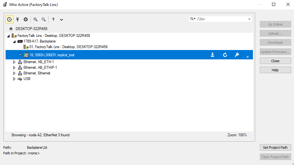
In the Communications menu, click Who Active. The FactoryTalk Linx dialog comes into view.
-
Select the 5069-L306ER and click the Go Online button. Make sure that you connect to the 5069 instance under the 1789-A17 backplane. Studio 5000 throws IP conflict errors (even when the A1/A2 addresses don’t conflict) when trying to configure the Ethernet ports if it is also connected through one.
-
If asked to update the PLC, select Download, and click OK through the prompts that come into view. When finished, the PLC goes back to remote run mode.
-
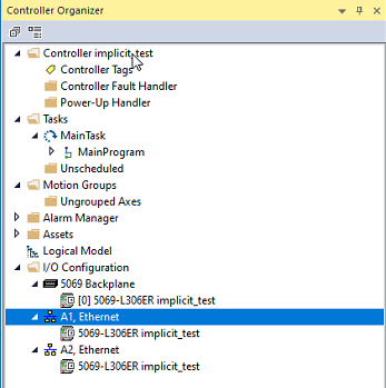
After the PLC is online, the Controller Organizer is updated and shows the Ethernet ports of the PLC.
-
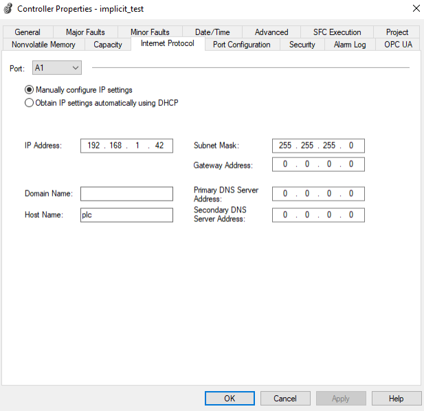
Select the PLC port that you connected the Automation1 controller to in step 3 (either A1 or A2), right-click, and select the Properties option. The Controller Properties dialog comes into view.
-
On the Controller Properties dialog, at the minimum, fill in the IP Address and Subnet Mask fields. When you are finished, click Apply then OK.
-
If the PLC is in RUN mode, you will get a warning that your IP address change can be a problem. Click OK.
-
Explicit Messaging Test
The procedure in the drop-down that follows shows you how to test explicit messaging by getting the VendorId from the Automation1 controller.
-
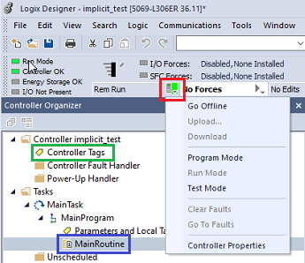
Click on the drop-down menu that is next to the controller state and select Go Offline.The drop-down icon is highlighted with a red square in the figure that follows.
-
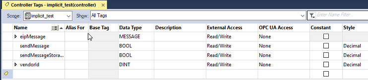
Right-click on Controller Tags and select Edit Tags. The Controller Tags dialog comes into view.
-
Enter the tag information as shown in the figure that follows.
-
In the Controller Organizer, right click on MainRoutine (the blue rectangle in image). Select Open to create an empty ladder logic diagram.
-
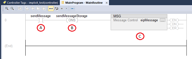
Create the ladder logic program that follows.
-
In the Bit tab, select Examine On (XIC).
-
In the Bit tab, select One Shot (ONS).
-
In the Input/Output tab, select Message (MSG).
-
Double-click on the question mark on each operand and enter the correct tag from step 3.
-
Set the XIC operand to sendMessage.
-
Set the ONS operand to sendMessageStorage.
-
Set the MSG operand to eipMessage.
-
-
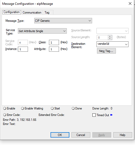
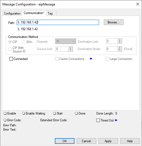
Configure the explicit message by clicking on the ellipses in the upper right corner of the MSG block. The Configuration tab comes into view.
-
For the Class, enter 1.
-
For the Instance, enter 1.
-
For the Attribute, enter 1.
-
For the Destination, enter vendorId.
-
Select the Communication tab and set the Path using this format:
<port>, <ipAddress>. -
The first part of the Path (before the comma) is the port to send the message over. If you are using port A1, enter 3. If you are using port A2, enter 4.
-
The second part of the Path is the Industrial Ethernet IP address of the Automation1 controller.
-
The test program is now done. Click on the drop-down from step 1 and select Go Online. When asked, select Download, and click through the prompts to return the PLC to the remote run mode.
-
In the ladder logic program, right-click on the XIC operand and select Toggle Bit. This activates the rung and triggers the MSG block to send the EtherNet/IP message.
-
The DN output signal of the MSG block is highlighted when the message response is ready.
-
Double-click on Controller Tags (the green rectangle from the first image). Make sure that the vendorId tag shows 935.
Implicit Messaging Test
The procedure in the drop-down that follows shows you how to test implicit messaging by using AeroScript to communicate between the PLC and the test PC.
-
Copy the EDS file for the controller you are using to the test PC. The EDS files are in the EtherNetIp folder of the Automation1-MDK installation. This example uses an Automation1 iXC4.
-
In Studio 5000, select the Tools menu, and click on Device Description Installation Tool.
-
The wizard comes into view. Click Next.
-
Click the radio button next to Register a device description file(s) and click Next.
-
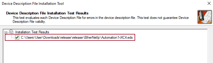
Click the radio button next to Register a single device description file. Click Browse… and select the
Automation1-iXC4.edsfrom step 1. Click Next. -
On the results screen, make sure that there is a green check mark next to the EDS file.
-
Register the Automation1 controller with Studio 5000 by clicking Next and Finish on the screens that come into view.
-
Click on the drop-down menu next to the controller state and select Go Offline. The drop-down icon is highlighted with a red square in the figure that follows.
-
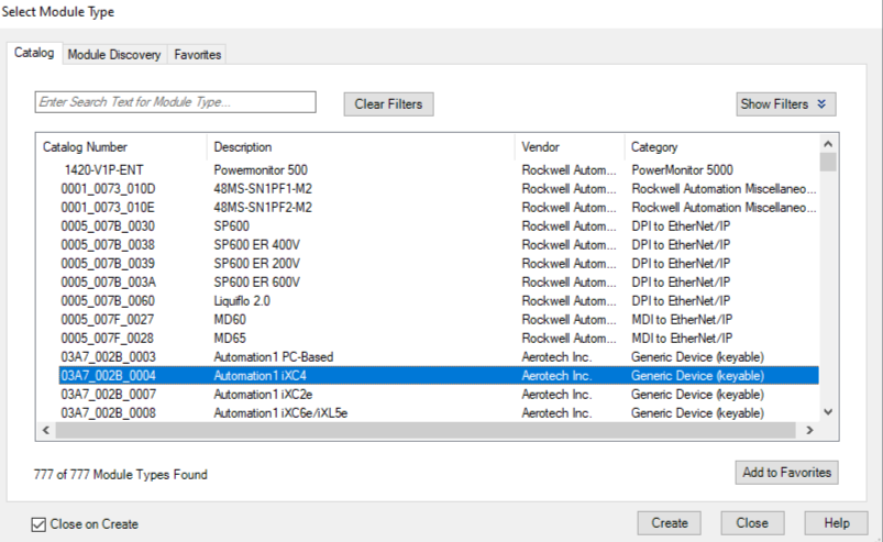
In the Controller Organizer, right-click on the PLC port that the Automation1 controller is connected to and select New Module. The Select Module Type dialog comes into view.
-
On the Select Module Type dialog, select the Automation1 controller that is the same as the controller you connected to the PLC. The figure above creates a connection to an Automation1 iXC4. After you have selected the correct controller, click the Create button. The New Module dialog comes into view.
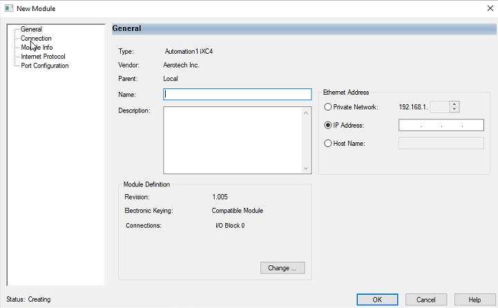
-
On the New Module dialog, enter a name in the name field. Enter the Industrial Ethernet IP address of the Automation1 controller in the IP address field. If you are using a 192.168.1.XXX IP address, you can use the Private Network section in the Ethernet Address section.
-
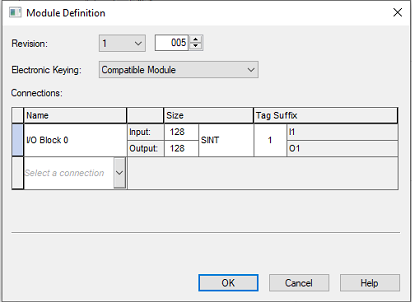
On the New Module dialog, select the connection(s) that you want by clicking on the Change … button. The Module Definition dialog comes into view.
-
In the Name column, select either I/O Block 0 or I/O Block 1 from one of the dropdowns.
-
Select SINT for the data type.
-
If you want to delete a connection, right-click on the left edge of the row and select Delete.
-
-
Enter a size between 1 and 496.
-
When you are done in the Module Definition dialog, click OK. Click Yes to the dialog that comes into view. Then click OK in the New Module dialog to finish adding the Automation1 controller. Close the Select Module Type dialog.
-
Create a periodic task to communicate with the Automation1 controller by right-clicking on the Tasks tab in the Controller Organizer and selecting New Task.
-
Give your new task a name and make sure the Type is set to Periodic. Set the length of the period.
-
-
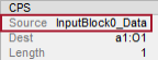
On the rung of the new periodic task, add one synchronous copy (CPS) instruction for each UDT that you imported. For example, if you are using Input Block 0 and Output Block 0 you would add 2 CPS instructions to your ladder logic program.
-
Configure parameters for input data.
-
For the first parameter, enter the data array of the input block you are using. This parameter value depends on the name that you chose for the controller in step 10.
-
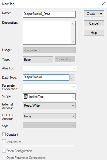
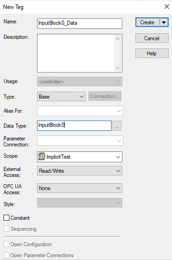
For the second parameter, right-click on the second dialog of the CPS instruction and create a tag for the destination data. Make sure the Data Type field is the same as the corresponding output block on your Automation1 controller.
-
For the third parameter, enter 1 for the size. The size argument for the CPS instruction is in units of the destination element. When you use 1 for the size, the PLC can copy all of the input block with just one CPS instruction.
-
-
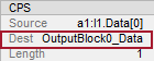
Configure parameters for output data.
-
For the first parameter, right-click on the first dialog of the CPS instruction, and create a tag for the source data. Make sure that the Data Type field is the same as the corresponding input block on your Automation1 controller.
-
For the second parameter, enter the output block you are using. This parameter value depends on the name that you chose for the controller in step 10.
IMPORTANT: The second parameter is
a1:O1and nota1:O1.Data[0], as it was for the input data. This is necessary to copy all of the output block with only one CPS instruction. -
For the third parameter, enter 1 for the size. The size argument for the CPS instruction is in units of the destination element. When you use 1 for the size, the PLC can copy all of the output block with just one CPS instruction.
-
-
-
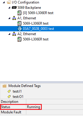
Make sure that the Automation1 controller is running.
-
Click on the drop-down from Step 8 and select Go Online. When asked, select Download and click through the prompts that come into view to return the PLC to remote run mode.
-
If all is configured correctly, the status dialog at the bottom of the Controller Organizer shows the Status as Running.
- Write an AeroScript program to read and write the Industrial Ethernet mappings for EtherNet/IP. A generic sample using input and output data is shown below. You might have to change the variable names based on your Industrial Ethernet mappings.
-
Execute your AeroScript program and make sure that the values in the Controller Tags tab are correct.
IMPORTANT: The size that you enter is the number of items of the selected data type from the previous step, not the number of bytes.
Program Example: AeroScript Industrial Ethernet Mappings
var $iii as integer = 0

while true
	for $iii = 0 to 4
		// Outputs
		CriticalSectionStart()
		$unsigned_int = 0xabcd
		$out_byte_array[0] = 1
		$out_byte_array[1] = 2
		$out_byte_array[2] = 3
		$pos_fbk_array[$iii] = $iii + 12.3
		$out_status_array[$iii] = 0x0F + $iii
		$vel_fbk_array[$iii] = $iii + 4.56
		CriticalSectionEnd()
		Dwell(0.5)
	end

	// Inputs
	$iglobal[0] = $signed_int
	$iglobal[1] = $in_byte_array[0]
	$iglobal[2] = $in_byte_array[1]
	$iglobal[3] = $in_byte_array[2]
	$iglobal[4] = $in_status_array[0]
	$iglobal[5] = $in_status_array[1]
	$iglobal[6] = $in_status_array[2]
	$iglobal[7] = $in_status_array[3]
	$iglobal[8] = $in_status_array[4]
	$rglobal[0] = $pos_cmd_array[0]
	$rglobal[1] = $pos_cmd_array[1]
	$rglobal[2] = $pos_cmd_array[2]
	$rglobal[3] = $pos_cmd_array[3]
	$rglobal[4] = $pos_cmd_array[4]
	$rglobal[5] = $vel_cmd_array[0]
	$rglobal[6] = $vel_cmd_array[1]
	$rglobal[7] = $vel_cmd_array[2]
	$rglobal[8] = $vel_cmd_array[3]
	$rglobal[9] = $vel_cmd_array[4]

	Dwell(1)
end


