Servo Loop Tuning Functions
The servo loop tuning functions let you tune the servo loop or bypass the servo loop to troubleshoot motor commutation. The functions let you set multiple servo loop gains at the same time and command current directly to the motor.
Open-loop Current
The open-loop current functions let you bypass the servo loop and directly command a current output to the motor. You can use these functions to troubleshoot or configure motor commutation.
Set the Constant Motor Current at a Fixed Electrical Angle
Use the TuningSetMotorAngle() function to generate an open-loop current command to the motor at a fixed electrical angle with the $angle argument. The three-phase motor outputs are calculated and held constant to position the motor shaft at the specified electrical angle. The offset specified by the CommutationOffset Parameter is added to the $angle argument before it is applied to the motor. If the axis is disabled, you can issue the TuningSetMotorAngle() function with a non-zero $current argument to enable the axis. For an axis under gantry control, the $current argument is applied to the $axis argument. For more information about the difference between physical and logical axes, refer to Gantry Control Methods on the Gantry Systems Overview page.
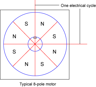
Most rotary motors have multiple electrical cycles per motor revolution, which means that the commanded electrical angle might not directly correspond to the angle of the motor shaft. The figure that follows shows the alignment of the magnetic poles for a typical eight pole brushless motor. One electrical cycle is defined as the progression from one north pole through its corresponding south pole up to the next north pole. In this case, there are four orientations of the motor shaft that would correspond to the same electrical angle.
Depending on the starting angle of the motor shaft with respect to the commanded electrical angle, the TuningSetMotorAngle() function can cause the motor to move by up to half an electrical cycle. For this reason, the Position Error Fault and Velocity Error Fault are suppressed when executing this function.
You can use the TuningSetMotorAngle() function to verify the sequencing and alignment of hall-effect switches or to troubleshoot commutation problems. The expected hall states for different motor electrical angles are in the table that follows. If your observed hall states are different from those in the table, use the CommutationOffset Parameter to compensate for misalignment.
Table: Hall States Expected at Different Commanded Electrical Angles
|
Commanded Electrical Angle |
Hall A State | Hall B State | Hall C State |
|---|---|---|---|
|
330° – 30° |
L |
L |
H |
|
30° – 90° |
L |
H |
H |
|
90° – 150° |
L |
H |
L |
|
150° – 210° |
H |
H |
L |
|
210° – 270° |
H |
L |
L |
|
270° – 330° |
H |
L |
H |
To disable the axis while the TuningSetMotorAngle() function executes, you can use a $current argument of 0, use the Disable() function, or use the Abort() function.
The TuningSetMotorAngle() function is an asynchronous motion function that does not cause the program to wait.
The example that follows commands a constant 0.8 amps to the motor at an electrical angle of 60 degrees on axis X.
TuningSetMotorAngle(X, 0.8, 60)
Generates an open-loop current command at a fixed electrical angle.
Arguments
$axis The axis on which to command current.
$current The current to output, specified in amperes.
$angle The electrical angle, specified in degrees. 360 degrees is one electrical commutation cycle of the motor.
Set the Constant Motor Current at a Rotating Electrical Angle
The TuningSetMotorCurrent() function can be used to generate an open-loop current command to the motor at a rotating electrical angle. The constant current is applied at an electrical angle that rotates based on the configured commutation method to maintain maximum torque on the motor. This causes the motor to spin as fast as possible based on the commanded current. For an axis under gantry control, the $current argument is applied to the $axis argument. For more information about the difference between physical and logical axes, refer to Gantry Control Methods on the Gantry Systems Overview page.
For a positive current, the motor will commutate in the forward direction. For a negative current, the motor will commutate in the reverse direction
Use the TuningSetMotorCurrent() function to test the commutation alignment with the steps that follow:
How to test commutation alignment
- Specify a forward (positive) current and note the achieved motor speed.
- Specify a reverse (negative) current and note the achieved motor speed.
- If the observed speeds are not similar, then there is likely a misalignment in commutation angle causing a difference in torque in the two directions. Adjust the CommutationOffset Parameter to correct this.
To disable the axis while the TuningSetMotorCurrent() function executes, you can use a $current argument of 0, use the Disable() function, or use the Abort() function. You can also call the overload with the $duration argument to disable the axis after the specified amount of time.
The TuningSetMotorCurrent() function is an asynchronous motion function that does not cause the program to wait.
The example that follows commands a constant 0.8 amps to the motor on axis X.
TuningSetMotorCurrent(X, 0.8)
Generates an open-loop current command at a rotating electrical angle.
Arguments
$axis The axis on which to command current.
$current The current to output, specified in amperes.
Generates an open-loop current command at a rotating electrical angle.
Arguments
$axis The axis on which to command current.
$current The current to output, specified in amperes.
$duration The amount of time to output current, specified in milliseconds. Specify 0 to output current continuously.
Set Gains
Set servo loop and feedforward gain parameters with the TuningSetServoLoopGains() and the TuningSetFeedforwardGains() functions. These functions let you set all of the servo loop gains at the same time during program execution. This prevents instability that can occur if you set each gain separately with parameter functions. These functions set the gains between executions of the servo loop to prevent changes from occurring in the middle of servo loop execution.
The function call specifies the gains to set and their respective values. For gains not specified, their values are unchanged.
Set Servo Loop Gain Values
HARDWARE: The TuningSetServoLoopGains() function is not compatible with the GL4 and XL4s drives.
You can use the function that follows to set the nine servo loop gain values. The ServoLoopGain enumeration has a field for each applicable gain that you can use in the $servoGains argument.
The example that follows sets servo loop gains K, Kiv, Kip, Kv, and Kpv at the same time on axis X. All other servo loop gains will not be modified.
TuningSetServoLoopGains(X, [ServoLoopGain.GainK, ServoLoopGain.GainKiv, ServoLoopGain.GainKip, ServoLoopGain.GainKv, ServoLoopGain.GainKpv], [0.007, 14.3, 14.3, 1, 1])
Sets the specified servo loop gain values on the specified axis.
Arguments
$axis The axis on which to set the gain values.
$servoGains An array of servo loop gains to set.
$servoGainValues An array of servo loop gain values to set.
| enum ServoLoopGain
GainK = 0 GainKiv = 1 GainKip = 2 GainKv = 3 GainKpv = 4 GainKip2 = 5 GainKsi1 = 6 GainKsi2 = 7 GainAlpha = 8 end |
Set Feedforward Gain Values
You can use the TuningSetFeedforwardGains() function to set the active value for the feedforward gain parameters that follow: FeedforwardGainAff, FeedforwardGainVff, FeedforwardGainPff, FeedforwardGainJff, and FeedforwardGainSff. The FeedforwardGain enumeration has a field for each applicable gain that you can use in the $feedforwardGains[] argument.
HARDWARE: With the GL4 and XL4s drives, the TuningSetFeedforwardGains() function can only set the FeedforwardGainAff Parameter and FeedforwardGainVff Parameter. For all other drives, the TuningSetFeedforwardGains() function can set all feedforward gain parameters.
When you set the active value of a feedforward gain parameter, it might require one or more milliseconds before it has an effect. But some feedback gains can change at a higher rate while synchronized to your next move. These higher rate gains are Aff and Vff. The feedforward gains, Pff, Jff, and Sff, cannot be changed at a higher rate. Thus if you set Pff, Jff, or Sff with one of the higher rate gains (Aff or Vff), all of the gains will be set at the normal 1 kHz rate.
IMPORTANT: Lookahead behavior for the TuningSetFeedforwardGains() function is different based on the gains that you specify. If you specify Aff or Vff, then lookahead can look through this function. If you specify Pff, Jff, or Sff, then lookahead cannot look through this function.
The examples that follow show you the behavior of the TuningSetFeedforwardGains() function when you set feedforward gains.
Program Example
// On axis X, set Aff = 10.0 at a higher rate on your next move.
TuningSetFeedforwardGains(X, [FeedforwardGain.GainAff], [10.0])

// On axis X, set Aff = 10.0 and Vff = 20.0 at a higher rate on your next move.
TuningSetFeedforwardGains(X, [FeedforwardGain.GainAff, FeedforwardGain.GainVff], [10.0, 20.0])

// On axis X, set Vff = 20.0 and Jff = 30.0 at the normal, 1 kHz rate.
TuningSetFeedforwardGains(X, [FeedforwardGain.GainVff, FeedforwardGain.GainJff], [20.0, 30.0])
If you want to set gains for two or more axes at a higher rate, set them before your next move. Refer to the example that follows:
Program Example
// On axis X, set Aff = 10.0 at a higher rate on your next move.
TuningSetFeedforwardGains(X, [FeedforwardGain.GainAff], [10.0])

// On axis Y, set Vff = 5.5 at a higher rate on your next move.
TuningSetFeedforwardGains(Y, [FeedforwardGain.GainVff], [5.5])

// Aff = 10.0 is set for axis X and Vff = 5.5 is set for axis Y at
// the start of this move regardless of which axes are specified.
MovePvt([X], [1], [2], 0.05)

// On axis X, set Vff = 20.0 at a higher rate on your next move.
TuningSetFeedforwardGains(X, [FeedforwardGain.GainVff], [20.0])

// Aff = 10.0 was previously set for axis X. Now, Aff = 10.0 and Vff = 20.0
// are set for axis X at the start of this move.
MovePvt([X], [1], [2], 0.05)
Sets the specified feedforward gain values on the specified axis.
Arguments
$axis The axis on which to set the gain values.
$feedforwardGains An array of feedforward gains to set.
$feedforwardGainValues An array of feedforward gain values to set.
| enum FeedforwardGain
GainAff = 0 GainVff = 1 GainJff = 2 GainPff = 3 GainSff = 4 end |


