Collecting Data
Use Data Collection to collect a set of time-series data in a real-time, deterministic way. You can look at plots of data that were collected from the controller in the Data Visualizer module.
Data collection occurs in real time, and the intervals between samples in one data collection instance are deterministic. The time between when data collection starts and when the first data point occurs, and the time between when the last data point is collected and when data collection stops is not completely deterministic. This is because start and stop operations occur from a non-real-time thread and have a variability of 10 milliseconds or more. You can collect only one set of data at a time on an Automation1 controller.
You can collect data by using the concepts that follow:
- Data Visualizer Module
- Application Data Collection Functions
- Data Collection Functions
- Motion Health®
- All of the Automation1 APIs
The pieces of information that you collect are called data signals. Data signals can be in the axis, task, or system category. All data signals are double-precision floating-point numbers. Some data signals represent enumerations or masks. Data signals include axis positions, axis-homed states, axis faults, I/O values, task states, task errors, and more.
The signals are collected from the drive at a slower rate than signals collected from the SMC because of the communication delay time with the drive. You can use the DriveMotionDelay axis status item to determine the delay time between the SMC signals and drive signals. Because virtual drives are emulated by the SMC without physical hardware, they have no communication delay.
Use the Data Visualizer Module to Collect Data
Use the Data Visualizer module to configure, collect, and look at data from the controller and also set the rate at which data collection occurs. You can also save, open, and look at plot files. To use the condensed version of this module in the Develop workspace, see Data Visualizer Module. To use the larger version of this module in the Visualize workspace, see Visualize Workspace. Refer to the pages that follow for more information:
- 1D Data Collection - includes procedures for how to configure and collect 1D (one-dimensional) data signals in the Data Visualizer module.
- 2D Data Collection - includes procedures for how to configure and collect 2D (two-dimensional) data signals in the Data Visualizer module.
- 3D Data Collection - includes procedures for how to configure and collect 3D (three-dimensional) data signals in the Data Visualizer module.
Data Collection Functions
Use the DataCollection*() functions to collect and write sampled data from an AeroScript program or library without using the Data Visualizer module. The plots that result are .dat files. The .dat file is a text file that uses ASCII![]() American Standard Code for Information
Interchange. This code assigns a number to each numeral
and letter of the alphabet. Information can then be transmitted between machines as a series of binary
numbers. characters to show the data that you collected. Position values are given in counts, and time values are given as seconds. The .dat file format is compatible with the Data Visualizer module. You can collect many types of data and specify the sample time at which the commands collect data.
American Standard Code for Information
Interchange. This code assigns a number to each numeral
and letter of the alphabet. Information can then be transmitted between machines as a series of binary
numbers. characters to show the data that you collected. Position values are given in counts, and time values are given as seconds. The .dat file format is compatible with the Data Visualizer module. You can collect many types of data and specify the sample time at which the commands collect data.
Configure Data Collection
Use the DataCollectionAdd*Signal() functions to configure the items for which data should be collected. When you add an item to data collection, you can use the DataCollectionStart() function to collect data. You can start and stop data collection from any task after it is configured. Use the DataCollectionReset() function to remove all the configured items from data collection.
function DataCollectionReset()
Resets the data collection configuration.
Configure Axis Signals
Use the functions that follow to configure the axis signals to collect for data collection.
function DataCollectionAddAxisSignal($axis as axis, $dataSignal as AxisDataSignal)
Adds an axis status signal to the data collection configuration.
Arguments
$axis The axis from which to retrieve the status signal value.
$dataSignal The data signal to retrieve.
function DataCollectionAddAxisSignal($axis as axis, $dataSignal as AxisDataSignal, $additionalData as integer)
Adds an axis status signal to the data collection configuration.
Arguments
$axis The axis from which to retrieve the status signal value.
$dataSignal The data signal to retrieve.
$additionalData Additional data for the specified status signal. This argument is required by some status signals.
| enum AxisDataSignal
PositionFeedback = 0 PositionCommand = 1 PositionError = 2 VelocityFeedback = 3 VelocityCommand = 4 VelocityError = 5 AccelerationCommand = 6 CurrentFeedback = 7 CurrentCommand = 8 CurrentError = 9 AnalogInput0 = 10 AnalogInput1 = 11 PositionCommandRaw = 12 VelocityCommandRaw = 13 AuxiliaryFeedback = 14 DigitalInput = 15 DigitalOutput = 16 WorkOffsetValue = 18 PhaseACurrentFeedback = 19 PhaseBCurrentFeedback = 20 EncoderSine = 21 EncoderCosine = 22 AnalogInput2 = 23 AnalogInput3 = 24 FrequencyResponseBefore = 25 FrequencyResponseAfter = 26 AnalogOutput0 = 31 AnalogOutput1 = 32 AnalogOutput2 = 33 AnalogOutput3 = 34 DriveMemoryInt32 = 35 DriveMemoryFloat = 36 DriveMemoryDouble = 37 PsoStatus = 38 DriveTimerDebug = 39 CoordinatedPositionTarget = 41 DriveStatus = 42 AxisStatus = 43 AxisFault = 44 AccelerationCommandRaw = 45 PositionCalibrationAll = 50 PositionFeedbackRollover = 63 PositionCommandRollover = 64 VelocityFeedbackAverage = 65 CurrentFeedbackAverage = 66 AxisParameter = 68 Backlash HomeState = 73 PositionCalibration2D = 74 NormalcyDebug = 75 TotalMoveTime = 76 PositionFeedbackDrive = 77 JerkCommandRaw = 78 ProgramPositionCommand = 79 PositionOffset = 80 PositionCommandRawBackwardsDiff = 82 VelocityCommandRawBackwardsDiffDelta = 83 PositionCommandDrive = 84 DriveStatusActual = 85 WorkOffsetIndex = 88 ProgramPositionFeedback = 89 JogTrajectoryStatus = 94 PingTest = 95 AccelerationTime = 109 DecelerationTime = 110 AccelerationRate = 111 DecelerationRate = 112 AccelerationType = 113 DecelerationType = 114 AccelerationMode = 115 DecelerationMode = 116 ProgramPosition = 124 DriveMemoryInt16 = 125 DriveMemoryInt8 = 126 SpeedTarget = 128 PositionCommandPacket = 131 DriveSmcMotionState = 132 PositionCommandRawCal = 140 VelocityCommandRawCal = 141 VelocityCommandDrive = 142 AccelerationCommandDrive = 143 GalvoLaserOutputRaw = 144 DriveInterfacePacketInt32 = 147 DriveInterfacePacketInt16 = 148 DriveInterfacePacketInt8 = 149 DriveInterfacePacketDouble = 150 DriveInterfacePacketFloat = 151 DriveInterfaceCommandCode = 152 AccelerationFeedback = 153 AccelerationCommandRawCal = 154 PositionCalibrationAllDrive = 155 BacklashTarget = 156 DriveMotionRate = 158 DriveMotionDelay = 159 CalibrationAdjustmentValue = 160 ServoRounding = 161 ServoLoopFeedforwardControlEffortRaw = 162 DriveInterfacePacketInfoBitValue = 164 AccelerationError = 165 SuppressedFaults = 167 DriveInterfacePacketStreamingData = 168 PositionCommandRawUnfiltered = 169 TransitionOffsetErrors = 170 PsoCounter0 = 171 PsoCounter1 = 172 PsoCounter2 = 173 PsoWindow0 = 174 PsoWindow1 = 175 DriveDataCaptureSamples = 176 PositionCommandGalvo = 178 FreezeVelocityCommand = 179 FreezeVelocityFeedback = 180 InternalPositionOffsets = 181 StatusHighLevelOffsetsLastMsec = 182 ProgramVelocityCommand = 183 ProgramVelocityFeedback = 184 DriveMotionDelayLive = 185 DriveCommunicationDelay = 186 DriveCommunicationDelayLive = 187 DriveInterfacePacketResponseInt32 = 189 DriveInterfacePacketResponseInt16 = 190 DriveInterfacePacketResponseInt8 = 191 DriveInterfacePacketResponseDouble = 192 DriveInterfacePacketResponseFloat = 193 DriveInterfacePacketBit = 194 DriveInterfacePacketResponseBit = 195 SpeedTargetActual = 196 PrimaryEnDatAbsolutePosition = 197 CoordinatedDistanceRemaining = 199 ServoLoopControlEffort = 201 PhaseAVoltageCommand = 208 PhaseBVoltageCommand = 209 PhaseCVoltageCommand = 210 AmplifierPeakCurrent = 211 FpgaVersion = 212 DriveTypeId = 213 PsoWindow0ArrayIndex = 214 PsoWindow1ArrayIndex = 215 PsoDistanceArrayIndex = 216 AmplifierTemperature = 217 PsoBitArrayIndex = 218 MxAbsolutePosition = 219 ServoUpdateRate = 220 SettlingTime = 221 InternalStatusCode = 222 FirmwareVersionMajor = 223 FirmwareVersionMinor = 224 FirmwareVersionPatch = 225 FirmwareVersionBuild = 226 DriveTimerDebugMax = 227 MarkerSearchDistance = 228 SafeZoneState = 230 PositionFeedbackGalvo = 234 PositionErrorGalvo = 235 LatchedMarkerPosition = 236 MoveReferencePosition = 237 MoveReferenceOffsetCutterRadius = 250 MoveReferenceOffsetCornerRounding = 251 MoveReferenceOffsetTotal = 252 PrimaryBissAbsolutePosition = 255 FaultPositionFeedback = 258 MotorCommutationAngle = 259 ExpansionBoardOption = 260 BusVoltage = 261 PiezoVoltageCommand = 262 PiezoVoltageFeedback = 263 DistanceLog = 264 TimeSinceReset = 273 MaximumVoltage = 274 CommandOutputType = 275 ServoLoopFeedforwardControlEffort = 290 LastTickCounter = 291 BoardRevision = 292 GalvoLaserOutput = 294 LaserOutputRawAdvance = 296 GalvoLaserOnDelay = 297 GalvoLaserOffDelay = 298 GalvoLaserPowerCorrectionOutput = 299 CapacitanceSensorRawPosition = 300 CalibrationAdjustmentState = 301 AccuracyCorrectionStartingPosition = 302 AccuracyCorrectionEndingPosition = 303 PositionCalibrationGalvo = 304 DriveCommandsDelayed = 309 DriveCommandsLost = 310 BusVoltageNegative = 325 ProcessorTemperature = 326 StoStatus = 327 InternalStatusTimestamp = 328 AnalogSensorInput = 329 MotorTemperature = 330 PrimaryBissStatus = 332 DriveAssert = 336 PsoExternalSyncFrequency = 337 EncoderSineRaw = 346 EncoderCosineRaw = 347 FpgaTemperature = 353 PrimaryEnDatStatus = 355 DriveTimerHighPriorityThread = 356 DriveTimerLowPriorityThread = 357 DriveTimerLowPriorityPacket = 358 DriveTimerServoPacket = 359 DriveTimerServoThread = 360 DriveTimerCurrentPacket = 361 DriveTimerCommonCoreThread = 362 DriveTimerServoCorePacket = 363 MultiplierOption = 365 PrimaryFeedback = 366 ServoLoopFeedbackInput0 = 367 ServoLoopFeedbackInput1 = 368 AccelerationSCurvePercentage = 371 DecelerationSCurvePercentage = 372 FaultSubcode = 376 ProcessorTemperatureMax = 378 DriveTimerHyperWireDma = 381 AmplifierTemperatureMax = 382 AuxiliaryEnDatAbsolutePosition = 383 AuxiliaryEnDatStatus = 384 AuxiliaryBissAbsolutePosition = 385 AuxiliaryBissStatus = 386 PsoOption = 387 DriveArraySize = 388 RatedMotorSupplyVoltageOption = 389 GantryMarkerDifference = 390 AbsoluteEncoderOption = 391 PrimaryFeedbackStatus = 392 AuxiliaryFeedbackStatus = 393 AmplifierStatus = 394 LatchedCwLimitPosition = 395 LatchedCcwLimitPosition = 396 LaserFpgaTransitionDelay = 397 HomeTargetPosition = 398 GantryRealignmentMoveTargetPosition = 399 GantryDriveControlRealignmentState = 400 PiezoAccumulatedCharge = 401 PiezoChargingTime = 402 PrimarySsiAbsolutePosition = 403 PrimarySsiStatus = 404 AuxiliarySsiAbsolutePosition = 405 AuxiliarySsiStatus = 406 PsoDistanceActiveDistance = 407 PsoWindow0ActiveLowerBound = 408 PsoWindow0ActiveUpperBound = 409 PsoWindow1ActiveLowerBound = 410 PsoWindow1ActiveUpperBound = 411 PsoWaveformActiveTotalTime = 412 PsoWaveformActiveOnTime = 413 PsoWaveformActivePulseCount = 414 PsoEventActiveBitValue = 415 DriveTimerDriveBasedControllerOutputDma = 419 DriveTimerPcieInboundFsm = 420 PrimaryFeedbackServo = 425 AuxiliaryFeedbackServo = 426 DriveStackUsage = 427 DriveInterfacePositionCommandPhysical = 434 DriveControlReason = 435 ShuntResistorTemperature = 436 SyncPortAPosition = 444 SyncPortBPosition = 445 HighSpeedOutputEncoderPosition = 446 AuxiliaryEncoderOutputPosition = 447 SyncPortAStatus = 448 SyncPortBStatus = 449 HighSpeedOutputEncoderStatus = 450 AuxiliaryEncoderOutputStatus = 451 DriveMemoryUInt32 = 454 DriveMemoryUInt16 = 455 DriveMemoryUInt8 = 456 CurrentLoopFeedbackControlEffort = 458 CurrentLoopFeedforwardControlEffort = 459 HighSpeedInput = 460 PositionCommandEncoder = 461 PositionFeedbackEncoder = 462 ServoLoopFeedbackControlEffort = 463 AnalogOutputHardwareStatus = 464 DigitalOutputHardwareStatus = 465 EnhancedScannerControlOption = 466 AnalogOutput4 = 467 AnalogOutput5 = 468 MoveReferenceOffsetCutterOffset = 471 LaserOutputRaw = 485 LaserOutput = 486 AutofocusError = 487 MotionRestrictionMask = 488 PWMPlusAmplifierType = 490 DriveTimerCurrentThread = 491 DriveTimerServoThread2 = 492 end |
Configure Task Signals
Use the functions that follow to configure the task signals to collect for data collection.
function DataCollectionAddTaskSignal($taskIndex as integer, $dataSignal as TaskDataSignal)
Adds a task status signal to the data collection configuration.
Arguments
$taskIndex The task from which to retrieve the status signal value.
$dataSignal The data signal to retrieve.
function DataCollectionAddTaskSignal($taskIndex as integer, $dataSignal as TaskDataSignal, $additionalData as integer)
Adds a task status signal to the data collection configuration.
Arguments
$taskIndex The task from which to retrieve the status signal value.
$dataSignal The data signal to retrieve.
$additionalData Additional data for the specified status signal. This argument is required by some status signals.
| enum TaskDataSignal
ProgramLineNumber = 17 CoordinatedFlags = 40 CoordinatedArcStartAngle = 53 CoordinatedArcEndAngle = 54 CoordinatedArcRadius = 55 CoordinatedArcRadiusError = 56 CoordinatedPositionCommand = 57 CoordinatedSpeedCommand = 58 CoordinatedAccelerationCommand = 59 CoordinatedTotalDistance = 60 CoordinatedPercentDone = 61 CoordinatedPositionCommandBackwardsDiff = 62 TaskParameter = 69 TaskError = 70 TaskWarning = 71 CoordinatedSpeedTargetActual = 86 DependentCoordinatedSpeedTargetActual = 87 TaskStatus0 = 90 TaskStatus1 = 91 TaskStatus2 = 92 SpindleSpeedTarget = 93 CoordinateSystem1I = 96 CoordinateSystem1J = 97 CoordinateSystem1K = 98 CoordinateSystem1Plane = 99 Mfo = 101 CoordinatedSpeedTarget = 102 DependentCoordinatedSpeedTarget = 103 CoordinatedAccelerationRate = 104 CoordinatedDecelerationRate = 105 CoordinatedAccelerationTime = 106 CoordinatedDecelerationTime = 107 TaskMode = 108 TaskState = 117 TaskStateInternal = 118 ExecutionMode = 121 EnableAlignmentAxes = 127 CoordinatedLaserOutput = 133 CoordinatedMotionRate = 145 CoordinatedTaskCommand = 146 EnableState = 166 LookaheadMovesExamined = 200 ProfileControlMask = 231 CoordinatedArcRadiusReciprocal = 253 MotionEngineStage = 254 CoordinatedTimeScale = 256 CoordinatedTimeScaleDerivative = 257 IfovSpeedScale = 266 IfovSpeedScaleAverage = 267 IfovGenerationFrameCounter = 268 IfovGenerationTimeOriginal = 269 IfovGenerationTimeModified = 270 IfovCoordinatedPositionCommand = 271 IfovCoordinatedSpeedCommand = 272 IfovCenterPointH = 276 IfovCenterPointV = 277 IfovTrajectoryCount = 278 IfovTrajectoryIndex = 279 IfovAttemptCode = 280 IfovGenerationFrameIndex = 281 IfovMaximumVelocity = 282 IfovIdealVelocity = 283 TaskInternalDebug = 284 IfovCoordinatedAccelerationCommand = 285 IfovFovPositionH = 286 IfovFovPositionV = 287 IfovFovDimensionH = 288 IfovFovDimensionV = 289 MotionBufferElements = 311 MotionBufferMoves = 312 MotionLineNumber = 313 MotionBufferRetraceMoves = 314 MotionBufferRetraceElements = 315 MotionBufferIndex = 316 MotionBufferIndexLookahead = 317 MotionBufferProcessingBlocked = 318 ActiveMoveValid = 319 TaskExecutionLines = 320 SchedulerTaskHolds = 321 SchedulerProgramLoopRuns = 322 SchedulerTaskBlocked = 323 CriticalSectionsActive = 324 AxesSlowdownReason = 331 TaskExecutionTime = 333 TaskExecutionTimeMaximum = 334 TaskExecutionLinesMaximum = 335 LookaheadDecelReason = 338 LookaheadDecelMoves = 339 LookaheadDecelDistance = 340 ProgramCounter = 341 StackPointer = 342 FramePointer = 343 StringStackPointer = 344 ProgramLineNumberSourceFileId = 349 MotionLineNumberSourceFileId = 350 ProgramLineNumberSourcePathId = 351 MotionLineNumberSourcePathId = 352 StringArgumentStackPointer = 354 CoordinatedAccelerationSCurvePercentage = 369 CoordinatedDecelerationSCurvePercentage = 370 DependentCoordinatedAccelerationRate = 373 DependentCoordinatedDecelerationRate = 374 CriticalSectionTimeout = 375 CommandQueueCapacity = 421 CommandQueueUnexecutedCount = 422 CommandQueueTimesEmptied = 423 CommandQueueExecutedCount = 424 CommandQueueLineNumber = 452 TaskReal = 469 TaskInteger = 470 MotionRestrictionAllowSectionsActive = 489 end |
Configure System Signals
Use the functions that follow to configure the system signals to collect for data collection.
function DataCollectionAddSystemSignal($dataSignal as SystemDataSignal)
Adds a system status signal to the data collection configuration.
Arguments
$dataSignal The data signal to retrieve.
function DataCollectionAddSystemSignal($dataSignal as SystemDataSignal, $additionalData as integer)
Adds a system status signal to the data collection configuration.
Arguments
$dataSignal The data signal to retrieve.
$additionalData Additional data for the specified status signal. This argument is required by some status signals.
| enum SystemDataSignal
VirtualBinaryInput = 46 VirtualBinaryOutput = 47 VirtualRegisterInput = 48 VirtualRegisterOutput = 49 Timer = 51 TimerPerformance = 52 GlobalReal = 67 CommunicationRealTimeErrors = 81 LibraryCommand = 119 DataCollectionSampleTime = 120 DataCollectionSampleIndex = 129 ModbusClientConnected = 134 ModbusServerConnected = 135 ModbusClientError = 136 ModbusServerError = 137 StopWatchTimer = 157 ScopetrigId = 163 EstimatedProcessorUsage = 177 DataCollectionStatus = 188 SignalLogState = 198 SafeZoneViolationMask = 207 SafeZoneActiveMask = 229 ModbusClientInputWords = 240 ModbusClientOutputWords = 241 ModbusClientInputBits = 242 ModbusClientOutputBits = 243 ModbusClientOutputBitsStatus = 244 ModbusClientOutputWordsStatus = 245 ModbusServerInputWords = 246 ModbusServerOutputWords = 247 ModbusServerInputBits = 248 ModbusServerOutputBits = 249 SystemParameter = 265 ThermoCompSensorTemperature = 305 ThermoCompControllingTemperature = 306 ThermoCompCompensatingTemperature = 307 ThermoCompStatus = 308 GlobalInteger = 345 AliveAxesMask = 348 SignalLogPointsStored = 377 ControllerInitializationWarning = 379 StopWatchTimerMin = 416 StopWatchTimerMax = 417 StopWatchTimerAvg = 418 EthercatEnabled = 428 EthercatError = 429 EthercatTxPdo = 430 EthercatTxPdoSize = 431 EthercatRxPdo = 432 EthercatRxPdoSize = 433 EthercatState = 437 ModbusClientEnabled = 438 ModbusServerEnabled = 439 HyperWireExternalSynchronizationActive = 440 HyperWireExternalSynchronizationFrequency = 441 HyperWireExternalSynchronizationLagging = 442 HyperWireExternalSynchronizationAdjustmentNanoseconds = 443 CallbackSlotProcessingState = 453 ControllerAssertCount = 457 VirtualBinaryInputBit = 472 VirtualBinaryOutputBit = 473 EtherNetIpAdapterEnabled = 474 EtherNetIpAdapterConnected = 475 EtherNetIpAdapterError = 476 EtherNetIpAdapterInputBlock0Size = 477 EtherNetIpAdapterInputBlock1Size = 478 EtherNetIpAdapterOutputBlock0Size = 479 EtherNetIpAdapterOutputBlock1Size = 480 EtherNetIpAdapterInputBlock0 = 481 EtherNetIpAdapterInputBlock1 = 482 EtherNetIpAdapterOutputBlock0 = 483 EtherNetIpAdapterOutputBlock1 = 484 end |
Start and Stop Data Collection
After you have configured data collection, use the function that follows to start data collection. Use the $controllerFileName argument to specify the name and location for the .dat file.
function DataCollectionStart($controllerFileName as string, $numSamples as integer, $sampleTime as real)
Starts real-time data collection.
Arguments
$controllerFileName The path, file name, and extension of the file on the controller file system to write data samples.
$numSamples Specifies the number of data samples to collect.
$sampleTime Specifies the sample time in milliseconds.
The $numSamples argument specifies the number of samples collected by data collection. The $sampleTime argument specifies the number of milliseconds between each sample that is collected. You can convert a sample frequency to a sample time with the formula that follows.

For example, to collect data with a sample rate of 20 kHz, specify a value of (1.0 / 20.0) or 0.05 for the $sampleTime argument. For more information about sample rates that the controller supports, refer to Data Collection Rates.
You can determine the duration of data collection with the formula that follows.

Use the DataCollectionItems Parameter and the DataCollectionPoints Parameter to configure the amount of controller memory that is available for data collection. To determine how much memory is available for data collection, use the formula that follows.

Memory allocation is necessary for collecting data. If the memory allocation does not complete correctly, a memory allocation error occurs. If memory resources are low, you can decrease the value of the DataCollectionItems parameter and the DataCollectionPoints parameter to release memory for other Automation1 features.
When you issue the DataCollectionStart() function, the controller continues to collect data for the specified number of samples. You can use the DataCollectionStop() function to stop data collection before the controller has collected the specified number of samples.
function DataCollectionStop()
Stops real-time data collection.
Data Collection Example
The example that follows shows you how to collect data with the DataCollection*() functions.
Program Example: Using Data Collection Functions
#define DATA_RATE      1.0 // kHz
#define DATA_DURATION  5.0 // seconds

DataCollectionReset()

DataCollectionAddAxisSignal(X, AxisDataSignal.PositionCommand)
DataCollectionAddAxisSignal(X, AxisDataSignal.VelocityCommand)
DataCollectionAddAxisSignal(X, AxisDataSignal.AccelerationCommand)

DataCollectionStart("results.dat", DATA_DURATION * DATA_RATE * 1000.0, 1.0 / DATA_RATE)
Other Ways to Collect Data
Signal Log is a monitoring and diagnostic tool that is included in the Motion Health® module. When enabled, Signal Log continuously collects diagnostic data and monitors the data for Signal Log trigger events. When a Signal Log trigger event occurs, Signal Log automatically saves the diagnostic data to a .dat file. You can open the .dat file in the Data Visualizer module.
You can perform data collection with all of the Automation1 APIs.
You can write an AeroScript program or library that collects information from the controller and then saves the information to a file. You can create a deterministic sample interval of 1 millisecond or multiples of 1 millisecond by issuing the CriticalSectionStart(), CriticalSectionEnd(), and Dwell() functions in a critical section of your program. Refer to the example that follows.
Program Example: Collect Status in a Critical Section and Save Results to a File
var $file as handle
var $values[1000] as real
var $index as integer

CriticalSectionStart()
for $index = 0 to (length($values) - 1)
        $values[$index] = StatusGetAxisItem(@0, AxisStatusItem.PositionCommand)
        Dwell(0.001)
end

$file = FileOpenText("results.dat", FileMode.Overwrite)

for $index = 0 to (length($values) - 1)
        FileTextWriteString($file, RealToString($values[$index]) + "\n")
end

FileClose($file)
CriticalSectionEnd()
Data Collection Rates
When you configure data collection, you specify a sample time in milliseconds. If you specify a data collection rate of 1 kHz (1 msec) or faster, you must specify one of the values that follow for the sample time:
-
1 msec (1 kHz)
-
0.2 msec (5 kHz)
-
0.1 msec (10 kHz)
-
0.05 msec (20 kHz)
-
0.01 msec (100 kHz) This collection rate is available only on the PC-based controller.
-
0.005 msec (200 kHz) This collection rate is available only on the PC-based controller.
Automatically Collected Signals During Data Collection
When collecting data, Studio automatically adds a set of signals to the data collection configuration for axes that have at least one configured signal. These signals are:
-
Velocity Command
-
Velocity Feedback
-
Velocity Error
-
Acceleration
 The change in velocity as a function of time. Command
 -
Acceleration
The change in velocity as a function of time. Error -
Acceleration
The change in velocity as a function of time. Feedback -
Current Command
-
Current Feedback
-
Current Error
-
Axis Status
-
Drive Status
These signals are only automatically included at data collection rates of 1 kHz or slower. By default, the signals are not visible on the resulting plot. You can display the signals on the plot using the Edit Plot dialog and clicking the Visibility icon next to the signal.
Data Collection Limitations
- The rate of Data Collection is limited to the servo loop update rate of the drive associated with that axis. Refer to the hardware manual for your drive to find the servo loop update rate.
- If you collect data on a virtual axis, make sure that the data collection rate is 1 kHz or slower. Virtual axes do not support collecting some signals at rates greater than 1 kHz.
- If the controller finds an error during data collection, some data signals might report NaN (not a number).
- Make sure that real-time errors do not occur on the controller during data collection. Real-time errors can also cause signals to report as NaN. You can review real-time errors by retrieving the
Communication Real Time Errorssystem status item. You can also look at the Controller tab of the Status Utility.
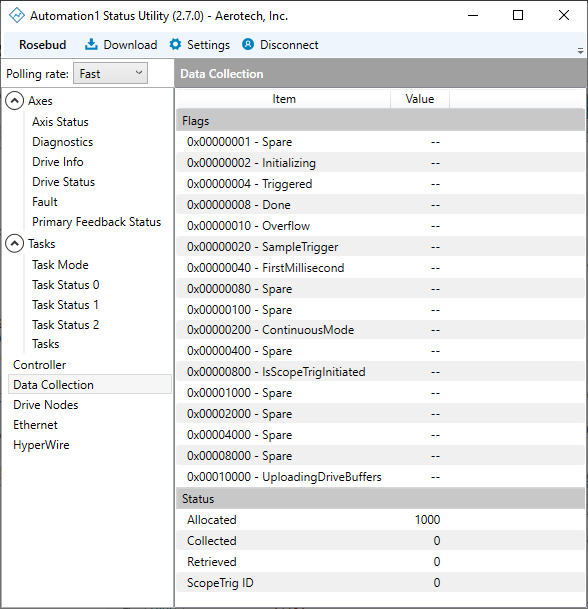
Data Collection Status
To get information about data collection, use the status items that follow:
- Data Collection Sample Time
- Data Collection Sample Index
- Data Collection Status
- Scopetrig Id
Use the Automation1 Status Utility to see Data Collection status on the Data Collection tab.