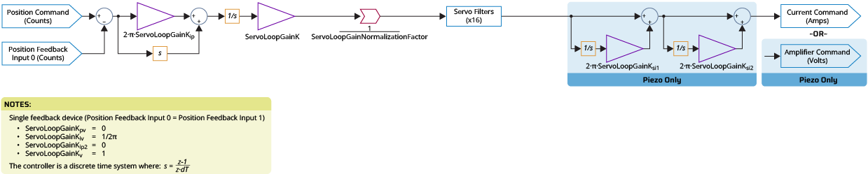
Servo Loop Block Diagram - Single Feedback PI
The diagram that follows shows the servo loop for a single feedback PI controller. It is for spring-like systems such as flexure-based piezo stages and the Yaw (Theta) axis of a rigid H-bridge gantry.
The units of the servo loop output depend on the type of axis being controlled. Refer to the table that follows.
Table: Servo Loop Axis Type, Output, and Units
| Axis Type | Servo Loop Output and Units |
|---|---|
|
Piezo axis |
Amplifier command in Volts. |
|
Stepper axis |
Commutation angle in microsteps. |
|
All other axes |
Current command in Amps. When the servo loop output is a current command, the current loop is used to generate the amplifier command in Volts. For more information, refer to Digital Current Loop Block Diagram. |
IMPORTANT: The units of ServoLoopGainK Parameter are determined by the ServoLoopGainNormalizationFactor. If ServoLoopGainNormalizationFactor is configured correctly, the units of ServoLoopGainK are in engineering stiffness units ([N/mm], [(Nm/rad], etc.). Refer to ServoLoopGainNormalizationFactor Parameter for more information.
Tip: For information on how to set the parameters, refer to the Help topic for each parameter.
Figure: Servo Loop Block Diagram - Single Feedback PI