Joystick Interface
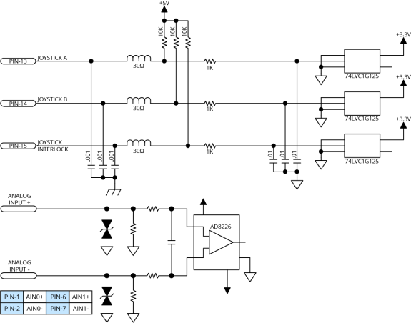
The Joystick Interface uses the two analog inputs and three dedicated inputs on the Analog I/O connector. Joystick operation requires that the two analog inputs be configured as single-ended inputs. The joystick interface is shown in Joystick Interface Inputs Schematic. Joystick Cable Wiring Schematic shows you how to connect a joystick to the Analog I/O connector.
Table 2-49: Joystick Interface Pins on the Analog I/O Connectors
|
Pin # |
Description |
In/Out/Bi |
|---|---|---|
|
1 |
Analog Input 0+ |
Input |
|
2 |
Analog Input 0- |
Input |
|
6 |
Analog Input 1 + |
Input |
|
7 |
Analog Input 1 - |
Input |
|
11 |
+5 V (500 mA maximum) |
Output |
|
12 |
Ground |
N/A |
|
13 |
Joystick Button A (Digital Input 16) |
Input |
|
14 |
Joystick Button B (Digital Input 17) |
Input |
|
15 |
Joystick Interlock (Digital Input 18) |
Input |
Figure 2-45: Joystick Interface Inputs Schematic
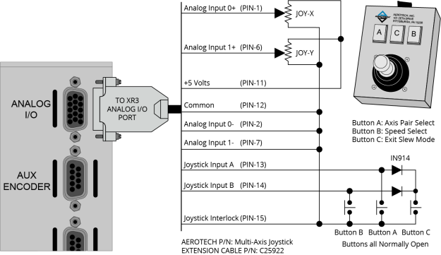
Aerotech Multi-Axis Joystick (NEMA12 (IP54) rated) is powered from 5 V and has a nominal 2.5 V output in the center detent position. Three buttons are used to select axis pairs and speed ranges. An optional interlock signal is used to indicate to the controller that the joystick is present. Joystick control will not activate unless the joystick is in the center location. Third party devices can be used provided they produce a symmetric output voltage within the range of -10V to +10V.
Refer to Automation1 Help for programming information about how to change joystick parameters.
Figure 2-46: Joystick Cable Wiring Schematic