Electrical Installation
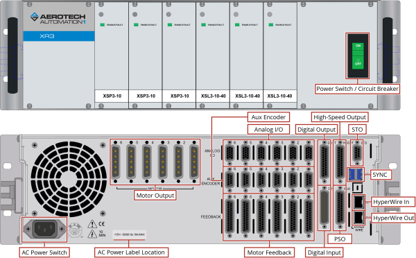
Motor, power, control and position feedback cable connections are made to the rear of the iXR3/XR3.
A combination power switch/circuit breaker is located on the front of the iXR3/XR3. This breaker is connected to the incoming AC power and provides protection to the iXR3/XR3 system in case of severe overloads. This breaker is selected to meet the maximum current requirements of the iXR3/XR3 system and is normally a 10 A breaker.
Figure 2-1: iXR3 Connection Overview
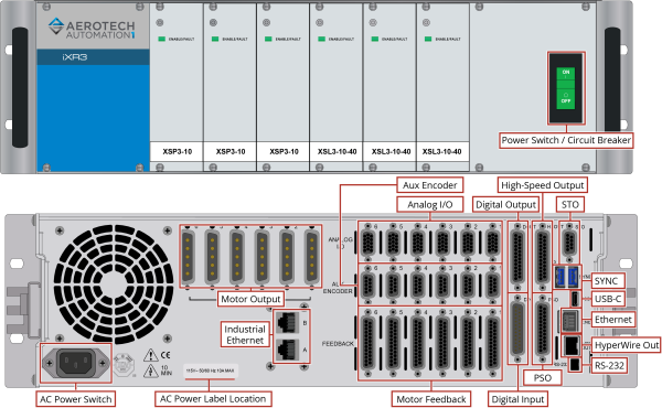
Figure 2-2: XR3 Connection Overview
All low voltage connections must be made using cables and wires sized for the maximum currents that will be carried. Insulation on these cables and wires must be rated at 300 V if this wiring can come into contact with wiring operating above 100 V (AC and motor wiring). Low voltage wiring should not be bundled with AC and motor wiring to minimize signal disturbances due to EMI interference and coupling.
IMPORTANT: The machine integrator, OEM or end user is responsible for meeting the final protective grounding requirements of the system.
DANGER: Disconnect power before you do maintenance to the equipment. Wait at least ten (10) minutes after removing the power supply before doing maintenance or an inspection. Otherwise, there is the danger of electric shock.
WARNING: Before powering on the iXR3/XR3, verify that all drive modules and cables to the iXR3/XR3 have been properly installed. Refer to the remaining chapters of this manual for installation and configuration procedures.
Confirm that the AC power is the correct voltage before turning on power to the iXR3/XR3.