Electrical Specifications
The electrical specifications for the drive rack are listed in Electrical Specifications and the electrical specifications for the servo amplifiers in PWM Amplifier Electrical Specifications (XSP3/XSP3+) and Linear Amplifier Electrical Specifications (XSL3).
IMPORTANT: These electrical specifications represent the maximum capability of a feature. System constraints can result in lower performance. For example, the motor output specifications are affected by the Bus supply, the number of axes that are operating at the same time, the type of motion, the AC Line voltage, and motor requirements.
The power label shows the factory-configured AC power requirements (iXR3/XR3 AC Power Label Location).
DANGER: Update the AC power label if you reconfigure the AC Input Voltage.
Figure 1-4: iXR3/XR3 AC Power Label Location
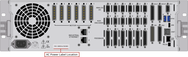
Table 1-2: Electrical Specifications
|
Description |
Option |
Specification |
|---|---|---|
|
±10 VDC (200 W Power Supply), bipolar |
||
|
±20 VDC (200 W Power Supply), bipolar |
||
|
±30 VDC (200 W Power Supply), bipolar |
||
|
±40 VDC (300 W Power Supply), bipolar |
||
|
±80 VDC (300 W Power Supply), bipolar |
||
|
+160 VDC, unipolar |
||
|
+320 VDC, unipolar |
||
|
120 VAC, 10 A Maximum |
||
|
240 VAC, 5 A Maximum |
||
|
100 VAC, 10 A Maximum |
||
|
200/208 VAC, 5 A Maximum |
||
|
AC input (Switch Selectable): AC Hi, AC Lo, Earth Ground (
Note: If the iXR3/XR3 contains an offline Bus power supply, the AC Input will be limited to one AC input range. |
||
|
32 A Peak |
||
|
+5 V provided on all axis feedback connectors for encoder, Hall, and limit power. |
||
|
The AC power cord serves as the mains breaker and provides 10 A, Supplemental Protection only. |
||
|
Internal Bus supply fusing. |
||
|
Amplifier Output short circuit protection. |
||
|
Peak and RMS over current limit. |
||
|
Over Temperature shutdown. |
||
|
Bus supply inrush current limit during initial power-on. |
||
|
Opto and transformer isolation between control and power stages. |
||
|
Power switch contains a power-on indicator. |
||
|
Individual Amplifier LED’s indicates drive enabled state. |
||
 ),
),
Table 1-3: PWM Amplifier Electrical Specifications (XSP3/XSP3+)
|
|
10 A |
20 A |
30 A |
|---|---|---|---|
|
Option Code |
-P1 or -P4 | -P2 or -P5 |
-P3 or -P6 |
|
10 APK |
20 APK |
30 APK |
|
|
5 A |
10 A |
10 A |
|
|
320 VDC |
|||
| 2 kHz | |||
|
20 kHz |
|||
|
0.5 mH |
|||
| 75 °C (All Amplifiers) | |||
|
1. AC voltage, Bus supply / load may result in significantly lower maximum peak currents. 2. Peak and continuous output current is load dependent. The controller will limit its output current based on velocity and motor resistance. 3. Selectable through parameters. |
|||
Table 1-4: Linear Amplifier Electrical Specifications (XSL3)
|
|
10 A |
|---|---|
|
Option Code |
-L1 |
| 10 A (1) | |
|
±40V bus (Apk) (2)(3)(4) |
1.5 A | 2.0 A | 1.0 A |
|
Power Dissipation (3)(4) |
120 W | 160 W | 120 W |
|
Peak Amplifier Power Dissipation per phase |
400 W |
| 0.42°C/W | 0.31°C/W | 0.42°C/W | |
| 75°C | |
|
Time to reach maximum temperature at maximum continuous power |
20 minutes |
|
(1) This specification depends on the motor supply voltage, the motor speed, and motor resistance. Contact an Aerotech sales engineer for more information. (2) This specification assumes a motor winding resistance of 0 Ω. (3) The first number is for a stationary AC or DC motor. The second number is for an AC motor that is in motion. The third number is for a stepper motor. (4) The specification will de-rate when the ambient temperature exceeds 25°C. NOTES:
|
|