PSO Interface [-EB1]
The Position Synchronized Output (PSO) signal is available on the -EB1 option board in two signal formats: TTL and Isolated.
The PSO signal is also available on the AUX I/O connector. Refer to Position Synchronized Output (PSO)
Table 3-15: PSO Specifications [-EB1]
|
Specification |
Value |
|
|---|---|---|
|
Output |
TTL |
5 V, 16 mA (max) |
|
Isolated |
5-24 V, 250 mA |
|
|
Maximum PSO Output (Fire) Frequency |
TTL |
12.5 MHz |
|
Isolated |
5 MHz |
|
|
Output Latency [Fire event to output change] |
TTL |
15 ns |
|
Isolated |
160 ns | |
Table 3-16: PSO Interface Connector Pinout [-EB1]
|
Pin # |
Description |
In/Out/Bi |
Connector |
|---|---|---|---|
|
1 |
PSO Output+ |
Output |
|
|
2 |
PSO Output- |
Output |
|
|
3 |
PSO Output (TTL) |
Output |
|
|
4 |
Ground |
N/A |
Table 3-17: PSO Interface Mating Connector Ratings [-EB1]
| Specification | Description | |
|---|---|---|
| Type | 4-Pin Terminal Block | |
| Part Numbers | Aerotech: ECK02399 | |
| Phoenix: 1768004 | ||
|
Conductor Cross Section |
Solid or stranded | 20...26 AWG (0.14...0.5 mm2) |
| Stranded, with ferrule, without plastic sleeve | 20...24 AWG (0.25...0.5 mm2) | |
| Conductor Insulation Strip Length | 8 mm (5/16 in) | |
|
(1) Refer to the manufacturer website for additional information. |
||
Isolated Signals
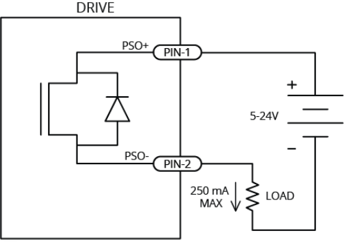
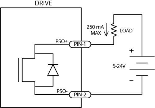
This output signal is a fully-isolated 5-24V compatible output capable of sourcing or sinking current. This output is normally open and only conducts current when a PSO fire event occurs.
The PSO Isolated Outputs are overload protected and will turn off if the maximum output current is exceeded.

|

|
TTL Signals
This output signal is a 5V TTL signal which is used to drive an opto coupler or general purpose TTL input. This signal is active high and is driven to 5V when a PSO fire event occurs.
Figure 3-12: PSO TTL Outputs Schematic

