Digital Outputs
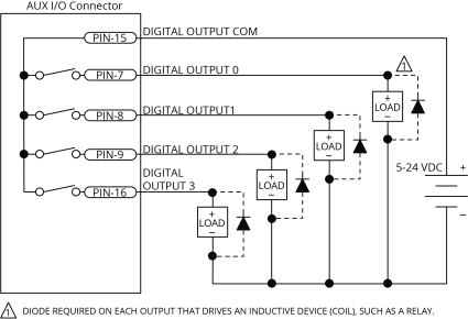
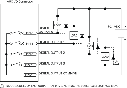
Optically-isolated solid-state relays drive the digital outputs. You can connect the digital outputs in current sourcing or current sinking mode but you must connect all four outputs in the same configuration. Refer to Digital Outputs Connected in Current Sourcing Mode and Digital Outputs Connected in Current Sinking Mode.
You must install suppression diodes on digital outputs that drive relays or other inductive devices. To see an example of a current sourcing output that has diode suppression, refer to Digital Outputs Connected in Current Sourcing Mode. To see an example of a current sinking output that has diode suppression, refer to Digital Outputs Connected in Current Sinking Mode.
The digital outputs are not designed for high-voltage isolation applications and they should only be used with ground-referenced circuits.
The digital outputs have overload protection. They will resume normal operation when the overload is removed.
Table 2-41: Digital Output Specifications
|
Digital Output Specifications |
Value |
|---|---|
|
Maximum Voltage |
24 V (26 V Maximum) |
|
Maximum Sink/Source Current |
250 mA/output |
|
Output Saturation Voltage |
0.9 V at maximum current |
|
Output Resistance |
3.7 Ω |
|
Rise / Fall Time |
250 µs (2K pull up to 24V) |
|
Reset State |
Output Off (High Impedance State) |