Hall-Effect Inputs
The Hall-effect switch inputs are recommended for AC brushless motor commutation but not absolutely required. The Hall-effect inputs accept 5 VDC level signals. Hall states (0,0,0) or (1,1,1) are invalid and will generate a "Hall Fault" axis fault.
Refer to Brushless Motor Powered Motor and Feedback Phasing for Hall-effect device phasing.
The Hall-effect sensors are not available when the ServoLoopSetup parameter is configured for stepper clock and direction outputs.
Table 2-10: Hall-Effect Feedback Pins on the Axis Connector
|
Pin # |
Description |
In/Out/Bi |
|---|---|---|
|
3 |
Signal Common |
Output |
|
4 |
Hall Effect Sensor A |
Input |
|
8 |
+5 V Supply (500 mA) |
Output |
|
16 |
Hall Effect Sensor B |
Input |
|
Stepper Clock |
Output | |
|
17 |
Hall Effect Sensor C |
Input |
|
Stepper Direction |
Output | |
|
21 |
Signal Common |
Output |
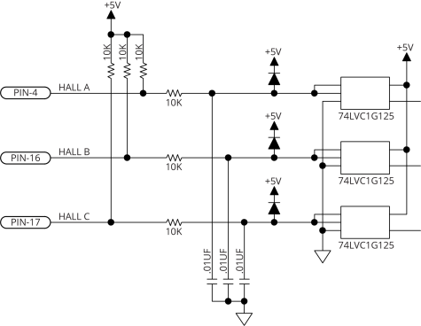
Figure 2-5: Hall-Effect Inputs Schematic