Stepper Clock and Stepper Direction Signals
The iXI4/XI4 uses the Stepper Clock and Stepper Direction outputs to interface to stepper motor drivers. Use the ServoLoopSetup parameter to configure this output type. The Hall-effect sensors are not available in this mode.
Table 2-7: Clock and Direction Pins on the Axis Connector
|
Pin # |
Description |
In/Out/Bi |
|---|---|---|
|
16 |
Hall Effect Sensor B |
Input |
|
Stepper Clock |
Output | |
|
17 |
Hall Effect Sensor C |
Input |
|
Stepper Direction |
Output |
Table 2-8: Stepper Clock and Stepper Direction Signal Output Specifications
|
Specification |
Value |
|---|---|
|
Output Voltage |
5V TTL |
| Maximum Output Frequency | 25 MHz |
|
Maximum Source / Sink Current |
±20 mA |
|
Clock Default State |
Logic Low (0 V) |
|
Direction Default State |
Logic Low (0 V) |
|
Maximum Clock Pulse Width |
25 µs |
| Minimum Clock Pulse Width | 20 ns |
To change the direction of the rotation of the motor, reverse the polarity of one of the phases. Reverse the A and A-N or B and B-N wires at the stepper motor driver.
Table 2-9: Stepper Direction Signal Output Polarity
|
Specification |
Value |
|---|---|
| Negative / CCW Direction |
Logic Low (0 V) |
| Positive / CW Direction |
Logic High (+5 V) |
Figure 2-3: Stepper Clock and Stepper Direction Timing
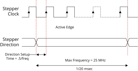
Figure 2-4: Stepper Clock and Stepper Direction Output Schematic