Mechanical Specifications
Mounting and Cooling
The controller must be installed in an enclosed control cabinet suitable for installation of power equipment. A minimum enclosure rating of IP54 is required to comply with safety standards. Make sure that there is sufficient clearance surrounding the controller for free airflow and for the routing of cables and connections. Consideration for items such as line reactors, line filters, and motor chokes or inductance should be made during the initial cabinet design phase.
Table: Mounting Specifications
|
|
iXI4/XI4 |
|
|---|---|---|
| Customer-Supplied Enclosure | IP54 Compliant | |
|
For DIN Rail Mounting, refer to DIN Rail Mounting |
||
| Weight | Standard |
0.60 kg |
| OEM | 0.25 kg | |
| Mounting Hardware | Standard | M4 [#8] screws (four locations, not included) |
| OEM |
M3 screws and M3 standoffs (seven locations) |
|
| Mounting Orientation | Vertical (typical) | |
| Dimensions | Refer to Dimensions | |
| Minimum Clearance | Airflow | ~25 mm |
| Connectors | ~100 mm | |
|
Minimum Airflow |
Standard | Provided by internal fan |
| OEM | 4.2 CMF (NOTE: Customer Supplied) | |
| Operating Temperature | Refer to Environmental Specifications | |
| Drive IP Rating | IP20 | |
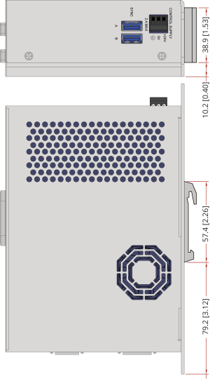
Dimensions
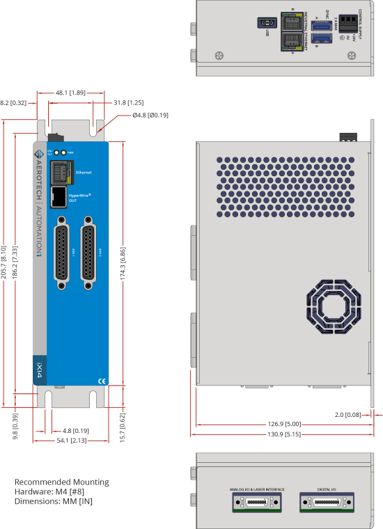
IMPORTANT: iXI4 and XI4 dimensions are the same. iXI4 is shown.
Figure: Dimensions [-2P1 (Standard 2-Axis)]
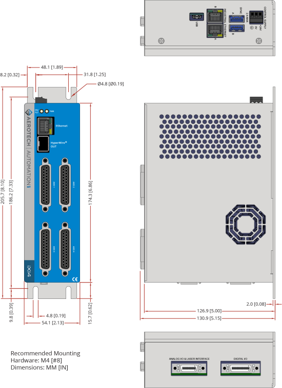
IMPORTANT: iXI4 and XI4 dimensions are the same. iXI4 is shown.
Figure: Dimensions [-4P1 (Standard 4-Axis)]
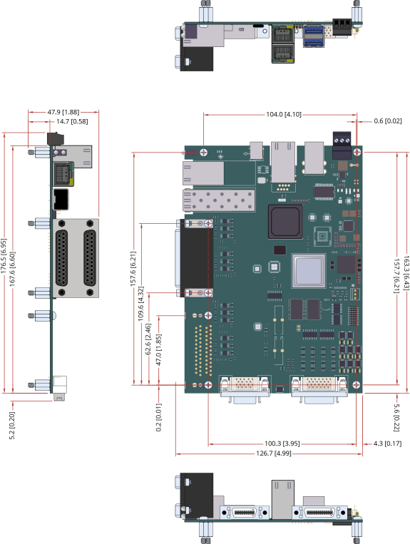
IMPORTANT: iXI4-OEM and XI4-OEM dimensions are the same. iXI4-OEM is shown.
Figure: Dimensions [-2P2 (OEM 2-Axis)]
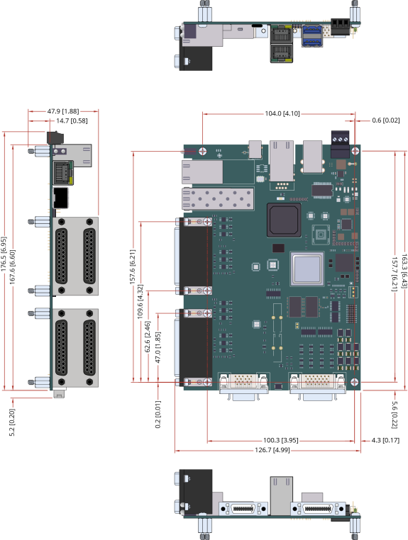
IMPORTANT: iXI4-OEM and XI4-OEM dimensions are the same. iXI4-OEM is shown.
Figure: Dimensions [-4P2 (OEM 4-Axis)]
DIN Rail Mounting
A DIN rail can only be used with the -2P1 or -4P1 options.
DIN Rail Mounting Procedure:
- Mount the DIN rail clip to the iXI4/XI4. The clip and #6-32 x 1/4 flat head screws are included in the DIN rail clip kit.
- Cut the DIN rail so one complete mounting hole extends beyond the last component at each end.
- Secure the DIN Rail to the mounting surface with #10-32 screws spaced every six inches.
NOTE: Do not install the DIN rail to the mounting surface with the components already attached. - Install all components on to the DIN rail.
Table: Mounting Parts
|
|
Aerotech P/N |
|---|---|
|
DIN Rail |
EAM00914 |
|
DIN Rail Clip Kit |
HyperWire-DIN |
Figure: Din Rail Clip Dimensions
OEM Mounting
- Secure the seven M3 standoffs to the mounting surface with M3 hex nuts. These hex nuts are not included with the drive.
NOTE: Do not install the standoffs to the mounting surface with the drive already attached.
- Attach the drive to the standoffs with the M3 screws. These screws are included with the drive.
Table: OEM Mounting Parts
|
|
Aerotech P/N |
|---|---|
| M3 Threaded Hex Standoff, 10 mm length | EIH01181 |
| M3 Philips Pan Head Screw, 8 mm length | HCY0003008 |