Sine Wave Encoder (Auxiliary) [-MX3 Option]
The Sine Wave Encoder option provides higher positioning resolution by subdividing the fundamental output period of the encoder into smaller increments. The amount of subdivision is specified by the AuxiliaryEncoderMultiplicationFactor parameter. Use Encoder Tuning to adjust the value of the gain, offset, and phase balance controller parameters to get the best performance. For more information, refer to Automation1 Help.
You cannot use the sine wave encoder on the auxiliary connector with the -MX3 multiplier option as an input to the PSO. The -MX3 option does not generate emulated quadrature signals from the auxiliary connector.
For the highest performance, use twisted pair double-shielded cable with the inner shield connected to signal common and the outer shield connected to frame ground. Do not join the inner and outer shields in the cable.
Table 2-35: Sine Wave Encoder Specifications
|
Specification |
Value |
||
|---|---|---|---|
| Primary | Auxiliary | ||
|
Input Frequency (max) |
450 kHz, 2 MHz |
450 kHz | |
|
Input Amplitude (1) |
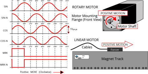
0.6 to 1.75 Vpk-pk |
||
|
Interpolation Factor (max) |
-MX2 |
65,536 |
N/A |
|
-MX3 |
65,536 |
16,384 |
|
|
-MX2/-MX3 Primary Encoder Channel Interpolation Latency |
800 nsec (analog input to quadrature output) |
||
|
Input Common Mode |
1.5 to 3.5 VDC |
||
|
(1) Measured as SIN(+) - SIN(-) or COS(+) - COS(-) |
|||