Digital Inputs
You can connect the digital inputs to current sourcing or current sinking devices but you must connect all four inputs in the same configuration. Refer to Digital Inputs Connected to Current Sourcing Devices and Digital Inputs Connected to Current Sinking Devices. The digital inputs are not designed for high-voltage isolation applications. They should only be used with ground-referenced circuits.
Table 2-44: Digital Input Specifications
|
Input Voltage |
Approximate Input Current |
Turn On Time |
Turn Off Time |
|---|---|---|---|
|
+5 V to +24 V |
6 mA |
10 µs |
43 µs |
Table 2-45: Digital Input Pins on the Auxiliary I/O Connector
|
Pin# |
Description |
In/Out/Bi |
|---|---|---|
|
17 |
Digital Input 0 / CCW EOT Input (1) |
Input |
|
18 |
Digital Input 1 / CW EOT Input (1) |
Input |
|
24 |
Digital Input Common |
Output |
|
25 |
Digital Input 2 / Home Input (1) |
Input |
|
26 |
Digital Input 3 |
Input |
|
(1) Software configured option |
||
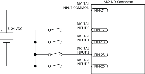
Figure 2-43: Digital Inputs Schematic (Aux I/O Connector)