Digital Outputs [-EB1]
Optically-isolated solid-state relays drive the digital outputs. You can connect the digital outputs in current sourcing or current sinking mode but you must connect all four outputs in a port in the same configuration. Refer to Digital Outputs Connected in Current Sourcing Mode [-EB1] and Digital Outputs Connected in Current Sinking Mode [-EB1].
The digital outputs are not designed for high-voltage isolation applications and they should only be used with ground-referenced circuits.
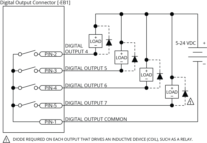
You must install suppression diodes on digital outputs that drive relays or other inductive devices. To see an example of a current sourcing output that has diode suppression, refer to Digital Outputs Connected in Current Sourcing Mode [-EB1]. To see an example of a current sinking output that has diode suppression, refer to Digital Outputs Connected in Current Sinking Mode [-EB1].
The digital outputs have overload protection. They will resume normal operation when the overload is removed.
Table 3-1: Digital Output Specifications [-EB1]
|
Digital Output Specifications |
Value |
|---|---|
|
Maximum Voltage |
24 V (26 V Maximum) |
|
Maximum Sink/Source Current |
250 mA/output |
|
Output Saturation Voltage |
0.9 V at maximum current |
|
Output Resistance |
3.7 Ω |
|
Rise / Fall Time |
250 µs (2K pull up to 24V) |
|
Reset State |
Output Off (High Impedance State) |
Table 3-2: Digital Output 1 Connector Pinout [-EB1]
|
Pin# |
Description |
In/Out/Bi |
Connector |
|---|---|---|---|
|
1 |
Output Common for Outputs 4-7 |
Output |
|
|
2 |
Output 4 (Optically-Isolated) |
Output | |
|
3 |
Output 5 (Optically-Isolated) |
Output | |
|
4 |
Output 6 (Optically-Isolated) |
Output | |
|
5 |
Output 7 (Optically-Isolated) |
Output | |
|
6 |
Output Common for Outputs 8-11 |
Output | |
|
7 |
Output 8 (Optically-Isolated) |
Output |
|
|
8 |
Output 9 (Optically-Isolated) |
Output |
|
|
9 |
Output 10 (Optically-Isolated) |
Output |
|
|
10 |
Output 11 (Optically-Isolated) |
Output |
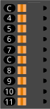
Table 3-3: Digital Output 2 Connector Pinout [-EB1]
|
Pin# |
Description |
In/Out/Bi |
Connector |
|---|---|---|---|
|
1 |
Output Common for Outputs 12-15 |
Output |
|
|
2 |
Output 12 (Optically-Isolated) |
Output | |
|
3 |
Output 13 (Optically-Isolated) |
Output | |
|
4 |
Output 14 (Optically-Isolated) |
Output | |
|
5 |
Output 15 (Optically-Isolated) |
Output | |
|
6 |
Output Common for Outputs 16-19 |
Output | |
|
7 |
Output 16 (Optically-Isolated) |
Output |
|
|
8 |
Output 17 (Optically-Isolated) |
Output |
|
|
9 |
Output 18 (Optically-Isolated) |
Output |
|
|
10 |
Output 19 (Optically-Isolated) |
Output |
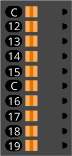
Table 3-4: Digital Output 1 and 2 Mating Connector Ratings [-EB1]
| Specification | Description | |
|---|---|---|
| Type | 10-Pin Terminal Block | |
| Part Numbers | Aerotech: ECK02395 | |
| Phoenix: 1700841 | ||
|
Conductor Cross Section |
Solid or stranded | 20...26 AWG (0.14...0.5 mm2) |
| Stranded, with ferrule, without plastic sleeve | 20...24 AWG (0.25...0.5 mm2) | |
| Conductor Insulation Strip Length | 8 mm (5/16 in) | |
|
(1) Refer to the manufacturer website for additional information. |
||
Figure 3-1: Digital Outputs Schematic [-EB1]

Figure 3-2: Digital Outputs Connected in Current Sourcing Mode [-EB1]
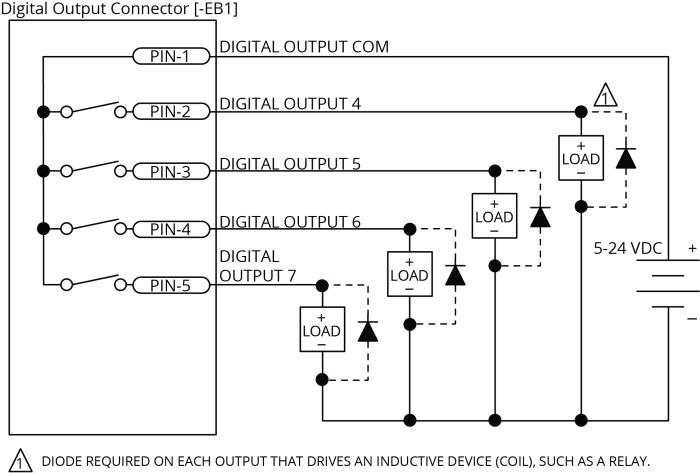
Figure 3-3: Digital Outputs Connected in Current Sinking Mode [-EB1]